9
b. Drill four (4) pilot holes, properly sized for the
non-corrosive fasteners (stainless steel, brass or
aluminum) to be used to secure the wall fl ange to
wall.
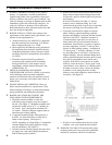
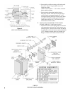
c. Attach four (4) ½” long threaded aluminum spacers
to the outer fl anges of the exterior telescoping
intake air duct wall fl ange with four (4) #10-32 x
¼” long stainless steel machine screws provided.
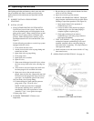
(See Figure 5).
d. Apply a ¼” thick continuous bead of silicone rubber
type caulking to the rear of the exterior telescoping
intake air duct wall fl ange approximately 1” from
duct.
e. Re-install exterior telescoping intake air duct and
secure to wall.
NOTE: Non-corrosive (stainless steel, brass or
aluminum) fasteners must be used.
f. Apply a bead of silicone rubber caulking to
perimeter of wall fl ange, where the wall and fl ange
join. Use a tool or your fi nger and apply pressure
while smoothing caulking to provide a weather-tight
seal.
4 INSTALLING VENT TUBE, ORIFICE PLATE
AND VENT TERMINAL COVER (See Figures 4
and 5).
a. The vent tube furnished has a standard length of
24”. This length is suitable for a wall thickness
from 5” to 15”.
b. To determine the proper length required, place a 24”
level horizontally across the exterior wall fl ange,
just below the aluminum spacers, measure the
distance between the outlet fl ange on the fan and
the level. Add 1” to this measurement for the total
length of the vent tube.
c. Measuring from the fl ange end of the vent tube,
mark the total length required. Cut off and discard
the remaining piece.
d. IMPORTANT! Before connecting vent tube to fan,
install the orifi ce plate and two (2) cerafi bre gaskets
on the fan outlet fl ange weld studs in the proper
order of assembly, gasket fi rst, orifi ce plate second
and remaining gasket last. (See Figures 4 and 5).
e. Insert the vent tube, fl ange fi rst, through the intake
air duct and secure to fan outlet fl ange with four (4)
¼” fl at washers, ¼” lock washers and ¼”-20 brass
hex nuts provided.
f. Position vent terminal cover over exterior intake air
duct. Insert end of vent tube into collar on rear of
vent terminal cover. Align four (4) holes on cover
with ½” long threaded aluminum spacers. Secure
vent terminal cover with four (4) #10-32 x ¼” long
stainless steel machine screws provided.
5 DO NOT REPLACE ENCLOSURE COVER until
boiler piping is completed and system is fi lled, vented
and checked for water leaks.
6 CONNECT SUPPLY AND RETURN PIPING TO
heating system.
OXYGEN CORROSION:
Oxygen contamination of the boiler water will cause
corrosion of the iron and steel boiler components,
which can lead to failure. As such, any system must
be designed to prevent oxygen absorption in the fi rst
place or prevent it from reaching the boiler. Problems
caused by oxygen contamination of boiler water are not
covered by Burnham’s standard warranty.
There are many possible causes of oxygen
contamination such as:
1. Addition of excessive make-up water as a result of
system leaks.
2. Absorption through open tanks and fi ttings.
3. Oxygen permeable materials in the distribution
system.
In order to insure long product life, oxygen sources
should be eliminated. This can be accomplished by
taking the following measures:
1. Repairing system leaks to eliminate the need for
addition of make-up water.
2. Eliminating open tanks from the system.
3. Eliminating and/or repairing fi ttings which allow
oxygen absorption.
4. Use of non-permeable materials in the distribution
system.
5. Isolating the boiler from the system water by
installing a heat exchanger.
a. For heating only, see Figure 6. Consult I=B=R
Installation Guides. Clearance between hot
water pipes and combustible material must not
be less than ½”.
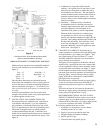
b. If this boiler is used in connection with
refrigeration systems, the boiler must be installed
so that the chilled medium is piped parallel
with the heating boiler using appropriate valves
to prevent the chilled medium from entering
the boiler, see Figure 7. Also consult I=B=R
Installation and Piping Guides. If this boiler
is connected to heating coils located in air
handling units where they may be exposed
to refrigerated air, the boiler piping must be
equipped with fl ow control valves to prevent
gravity circulation of boiler water during the
operation of the cooling system.
c. Pipe safety relief valve to suitable drain.
CAUTION: Safety relief valve should be piped
to an open drain — full size of discharge outlet on
relief valve without any provision of “shut-off”
between the relief valve and discharge into drain.
d. Install diaphragm type expansion tank (not
furnished) in system piping.


