


10
e. A hot water boiler installed above radiation level
must be provided with a low water cutoff device
as part of the installation.
If a low water cut-off is required, it must be
mounted in the system piping above the boiler.
The minimum safe water level of a hot water
boiler is just above the highest water containing
cavity of the boiler; that is, a hot water boiler
must be full of water to operate safely.
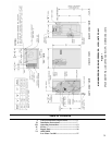
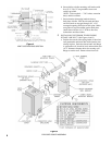
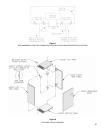
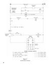
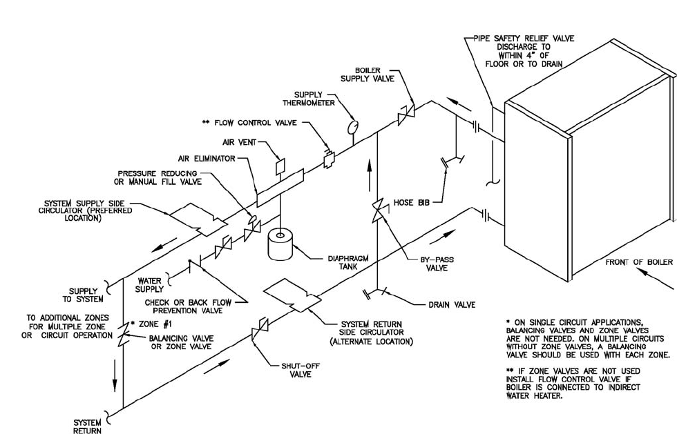
f. Use a boiler bypass if the boiler is to be
operated in a system which has a large volume
or excessive radiation where low boiler water
temperature may be encountered (i.e., converted
gravity circulation system, etc.). The bypass
should be the same size as the supply and return
lines with valves located in the by-pass and
supply outlet as illustrated in order to regulate
water fl ow for maintenance of higher boiler
water temperatures. See Figure 6.
Set the by-pass and boiler supply valves to a
half throttle position to start. Operate boiler
until the system water temperature is at a normal
operating range.
Adjust the valves to provide 180° to 200°F
supply water temperature. Opening the boiler
supply valve will raise the system temperature,
while opening the by-pass valve will lower the
system supply temperature.
If it is required to perform a long term pressure
test of the hydronic system, the boiler should fi rst
be isolated to avoid a pressure loss due to the
escape of air trapped in the boiler.
To perform a long term pressure test including
the boiler, ALL trapped air must fi rst be removed
from the boiler.
A loss of pressure during such a test, with no
visible water leakage, is an indication that the
boiler contained trapped air.
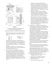
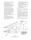
7 INSTALL BOILER FLUSH JACKET (See Figure
9).
a. Open jacket carton and locate side panels. Note that
jacket left side panel is not insulated and right side
panel is insulated.
b. Position the rear fl ange on jacket left side panel
behind the boiler back plate. Position fl ange support
notches over jacket support hooks on back panel
and engage jacket on both support hooks to keep the
panel from moving front to rear.
c. Position rear fl ange on jacket right side panel behind
upper and lower jacket support brackets. Engage
jacket with jacket support hooks in similar manner
as left side panel to provide proper positioning and
support.
d. Take jacket top and bottom panel from carton. Top
panel can be identifi ed by the front channel used to
Figure 6
RECOMMENDED BOILER PIPING