5
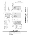
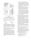
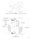
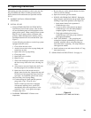
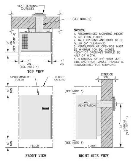
Minimum listed clearances from combustible materials
for non-closet installation or closet installation. (See
Figure 3).
Top — 6” *Left Side —1”
Rear — 0” Right Side — 1”
*Front — 2” Flue — 0”
Floor — 6”
Since the above dimensions are measured between
boiler jacket and combustible walls or ceiling, practical
service clearances for all external adjoining equipment
must be considered (see Figure 1). * A minimum of 24”
from left side and front jacket panel is recommended for
servicing.
In utility room installations, the door must be wide
enough to allow boiler to enter or to permit replacement
of another appliance in this room.
7 VENTILATION AND COMBUSTION AIR.
Provide provisions for combustion and ventilation air
in accordance with Section 5.3, Air for combustion
and ventilation, of the National Fuel Gas Code, ANSI
Z223.1 or applicable provisions of local building codes.
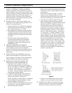
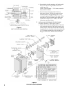
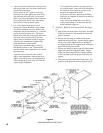
This boiler is equipped with a fan which produces
an induced draft through the unit. Combustion air is
pulled in from outdoors and the fl ue gases are exhausted
to the outdoors through the intake air/vent system. (See
Figure 4).
a. Combustion air is provided 100% from the
outdoors. Air is pulled in on all four sides of vent
terminal cover, through the air intake duct and to
the combustion area enclosure. The vent terminal
must be mounted on a fl at surface which is fl ush or
protrudes outward from the exterior wall. Avoid
recesses, niches or areas which might have reduced
fresh air circulation.
b. Ventilation — When the boiler is installed in
an unconfi ned space in a building of normal or
unusually tight construction, there is no additional
provision required to insure adequate air for
ventilation of the jacket or control compartment.
When the boiler is installed in a confi ned space,
two openings in a wall or door to an adjoining
interior area which has adequate air supply shall be
provided. One opening should be near the fl oor and
the other near the ceiling. Each shall have a free
area of not less than one (1) square inch for each
thousand (1000) BTU input to all appliances in the
boiler room. (See Figure 3).
8 CONNECT GAS SERVICE from meter to gas
control assembly in accordance with local piping codes
and requirements of gas company, see Figure 1. They
may require piping of larger size than 1/2” control
assembly connection, especially if run from meter is
long or includes several elbows.
This piping is to be supplied by the installer and must
include a trap, a ground joint union and a manual shut-
off valve upstream of the gas control assembly outside
of the jacket when codes require, see Figure 1. A pipe
thread compound resistant to the action of liquefi ed
petroleum gases should be applied to all threaded joints
in the gas piping. Pressure testing of the gas supply
piping, boiler and its connections is required before
placing the boiler in operation.
The boiler must be isolated from the gas supply piping
system by closing the manual shut-off during any
pressure testing at pressures equal to or less than 1/2
psig.
The boiler and shut-off valve must be disconnected
from the gas supply piping system during any pressure
testing at pressures greater than 1/2 psig.
RECOMMENDED SIZING OF GAS SUPPLY
PIPING TO BOILER shall be such as to provide the
required supply of gas without undue loss of pressure
between meter and the boiler. Gas supply piping should
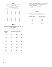
be sized in accordance with Tables, I, II and III.
The following shall be taken into account:
a. Allowable loss of pressure to assure a burner
manifold pressure of 3½” water.
b. Supply of gas to be provided in cubic feet.
c. Length of piping and number of fi ttings.
d. Specifi c gravity of gas.
e. Correction factor for specifi c gravity.
Figure 3
** A minimum of 24” from left side and front jacket
panel is recommended for servicing.
MINIMUM CLEARANCE TO COMBUSTIBLE SURFACES


