


8
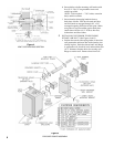
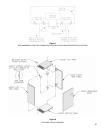
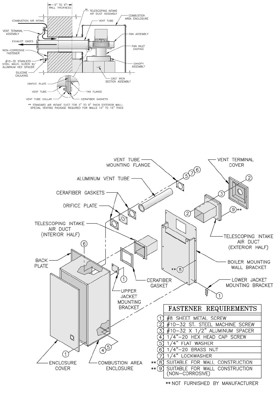
h. Secure boiler to boiler mounting wall bracket with
fi ve (5) ¼”-20 x ¾” long machine screws and
washers provided.
NOTE: Tools required — 7/16” socket, extension
bar(s) and drive ratchet
i. Secure interior telescoping intake air duct to
back plate of boiler. Pull duct forward until duct
and weld studs are engaged through 4½” x 5½”
rectangular opening and holes in back plate. Make
sure gasket is in place and fl at against back plate.
Attach duct with four (4) ¼”-20 brass hex nuts,
lockwashers and fl at washers.
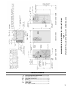
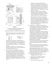
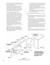
3 INSTALLING EXTERIOR TELESCOPING
INTAKE AIR DUCT (See Figures 4 and 5)
a. Position the exterior telescoping intake air duct into
wall penetration and insert duct inside interior duct
already in place. Push duct inward until wall fl ange
is against the wall, check for level and mark the four
(4) ¼” diameter clearance holes for securing wall
fl ange to exterior wall. Remove duct from wall.
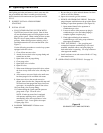
Figure 4
VENT SYSTEM CROSS SECTION
Figure 5
EXPLODED BOILER ASSEMBLY