


12
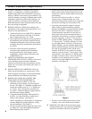
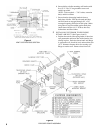
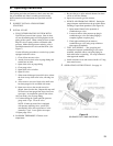
support the removable door. (See Figure 9). Place
jacket top panel over top side panels with ventilation
louvers to the left. Secure top panel with four (4) #8
x ½” long sheet metal screws provided.
e. Lift jacket bottom panel up to bottom of side panels
with front channel forward and ventilation louvers
to the left. Secure bottom panel with four (4) #8 x
½” long sheet metal screws provided.
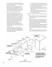
f. Install jacket removable door. Hold door parallel
with top of door slightly above fl at top panel. Insert
door between side panels. Lower door engaging
top panel reverse bend and lower panel fl ange in
the mating door fl anges. Door is now locked into
position.
g. Reverse procedure to remove door.
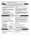
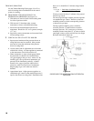
8 INSTALL ROOM THERMOSTAT on an inside
wall about four feet above fl oor. Never install
thermostat on an outside wall or where it will be
infl uenced by drafts, hot or cold water pipes, lighting
fi xtures, television, rays of the sun or near a fi replace.
Keep large furniture away from thermostat so there will
be free movement of room air around this control.
Heat anticipator in thermostat should be set at .4.
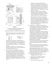
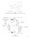
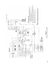
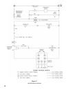
9 ELECTRIC WIRING INSTALLATION.
See Figures 11 and 12 for applicable wiring
diagram. A separate electrical circuit must be run
from the main electrical service with an over-current
device/disconnect in the circuit. A service switch is
recommended and may be required by some local
jurisdictions. The circuit should be run to the junction
box mounted on the front of the boiler back plate in the
control compartment (See Figure 1), and connected to
the proper leads therein. Wires from the low voltage
thermostat should be run to terminals R and G on
the transformer. Install wiring and ground boiler in
accordance with requirements of authority having
jurisdiction, or in absence of such requirements the
National Electrical Code, ANSI/NFPA 70.