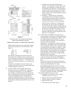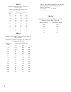
7
II. Installation Instructions
DETERMINE BEST MOUNTING LOCATION for boiler which meets site requirements outlined in Section I, pages 4
through 6.
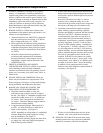
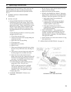
1 INSTALLING BOILER MOUNTING WALL
BRACKET (See Figure 5).
a. Locate wall bracket packed in miscellaneous parts
carton.
b. Hold wall bracket in desired location. On studded
walls, mounting bracket must be secured directly to
main vertical support studs. Interior wall coverings
such as paneling, plaster and drywall are not suitable
to support the unit’s weight. Place a 24” level
across top corners, adjust wall bracket until level.
Using the wall bracket as a template, mark the eight
(8) securing holes along the sides and the 4½” x
5¼” rectangular opening at the top. Remove wall
bracket from wall.
NOTE: The boiler mounting wall bracket is
suitable for two main methods of wall construction.
Masonry-built walls and stud-framed walls where
the main vertical support studs are on 16” centers
or alternately where adequate supports are added
between existing studs.
c. Drill eight (8) pilot holes, properly sized for the
fastener determined suitable for the type of wall
construction in the area where the boiler is to be
mounted (i.e., lag screw for wood, machine screw
with toggle for cinder block, etc.).
d. Before cutting rectangular opening on interior wall,
use a straight edge to draw an “X” inside the box
using the four (4) corners. Drill a hole in the center
of the “X” straight through the wall to the outside.
On the exterior wall draw a 4½” x 5¼” rectangular
box centered around the reference hole which
matches the rectangular box on the interior wall.
e. Cut along outside edge of lines on interior and
exterior surfaces of the wall and remove all
material within the rectangular box. Check the wall
penetration by inserting one-half of the telescoping
intake air duct through the opening. Remove any
jagged edges or webbing that prevents the duct from
penetrating through the wall or from being level.
Remove duct from wall penetration.
f. Lay the wall bracket face down. Apply a ¼” thick
bead of silicone rubber type caulking around the
rectangular opening approximately 1” from the
edge.
g. Reposition boiler mounting wall bracket on wall,
using a 24” level across top corners, level wall
bracket and secure to wall with suitable fasteners.
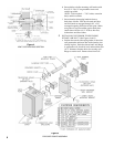
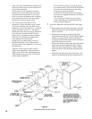
h. Attach lower R.S. jacket mounting bracket to right
side of boiler mounting wall bracket with sheet
metal screws provided. (See Figure 5)
2 INSTALLING BOILER AND INTERIOR
TELESCOPING INTAKE AIR DUCT
(See Figure 5)
a. Separate two halves of telescoping intake air duct.
Interior half of duct has a 1” wide rectangular gasket
fl ange with four (4) weld studs for attaching to
back plate of boiler. Exterior half of duct has the
9” square stainless steel wall fl ange for securing to
exterior wall. (See Figure 5)
NOTE: 1. Standard telescoping intake air duct,
part No. 6110301, is for wall thickness
from 5” to 9”.
NOTE: 2. Optional telescoping intake air duct, part
No. 6110302, is for wall thickness from
9” to 15”.
b. Insert interior half of duct into rectangular opening
and push it all the way back against wall plate.
c. Place 6” x 7” rectangular gasket on interior duct
fl ange and ¼” weld studs.
d. Remove boiler from packaging.
1. Remove surrounding packaging material from
boiler and skid.
2. Remove screws holding enclosure cover.
3. Remove enclosure cover.
4. Locate and remove two (2) lag screws which
secure back plate of boiler to skid. One is
located in the upper left corner of the controls
area and the second one is located in the lower
right corner under the gas burner.
5. Remove boiler from skid and set unit upright on
fl oor in front of installation site.
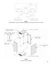
NOTE: On the back plate of the boiler is a “Z”
bracket approximately 10” long. When
the boiler is lifted into place, this bracket
must be lowered into the ½” wide x 11”
long slot at the top of the boiler mounting
wall bracket. (See Figures 4 and 5)
e. Attach upper RS jacket mounting bracket to the
upper corner of back plate. Loosen the two (2)
corner screws, position bracket with fl ange facing
forward and engage slots over screws. Re-tighten
screws to secure bracket. IMPORTANT: Bracket
must be installed before lifting boiler into position.
f. Lift boiler up into position. Make sure that “Z”
bracket is properly engaged into slot and is resting
on ¼” wide fl ange in front of slot before releasing
the weight of the boiler.
g. Move boiler slightly to the left or right to align the
fi ve (5) clearance holes in the back plate with the
fasteners on boiler mounting wall bracket.


