


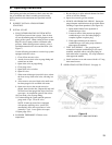
13
Safe lighting and other performance criteria were met with
the gas manifold and control assembly provided on the
boiler when the boiler underwent tests specifi ed in ANSI
Z21.13.
1 INSPECT INSTALLATION BEFORE
STARTING.
2 INITIAL START
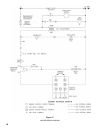
a. FILL ENTIRE HEATING SYSTEM WITH
WATER and vent air from system. Vent air from
all heat distributing units and all high points in the
piping of the system. When venting air from system
keep fi ll valve in open position to maintain water
pressure. Make certain pressure reducing valve is
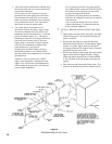
installed between the fi ll valve and the boiler. (See
Figure 7)
Use the following procedure on a series loop system
equipped with zone valves.
1. Close all but one zone valve.
2. Attach a hose to drain valve on purge fi tting and
extend hose to drain.
3. Open drain valve on purge fi tting.
4. Close purge valve.
5. Open relief valve on boiler.
6. Open fi ll valve.
7. When water discharges from relief valve, release
the lever on top of the relief valve, allowing it to
close.
8. Allow water to run out of drain valve until zone
has been purged of air and fi lled with water.
9. Open zone valve to the second zone to be
purged, then close the fi rst. Repeat this step until
all zones have been purged but always have one
zone open. At completion open all zone valves.
10. Close drain valve on purge fi tting.
11. Continue fi lling the system until the pressure
gauge reads 12 psi. Close fi ll valve.
NOTE: If make-up water line is equipped
with pressure reducing valve, system will
automatically fi ll to the set pressure of valve
(normally 12 psi). Leave globe valve open.
12. Open purge valve.
b. Set ROOM THERMOSTAT below room
temperature.
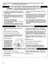
III. Operating Instructions
c. Be sure that gas to pilot and main burners has been
off for at least fi ve minutes.
d. Open valve on main gas line at meter.
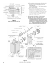
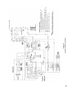
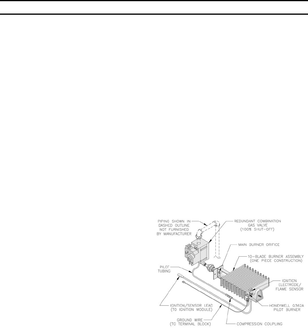
e. PURGE AIR FROM GAS PIPING. During the
purge adequate ventilation must be provided and no
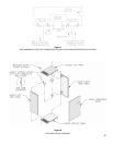
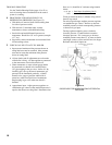
smoking or open fl ame permitted. (See Figure 10)
1. Open manual shutoff valve upstream of
combination gas valve.
2. Loosen or remove inlet pressure tap plug in
combination gas valve and when purging is
complete, tighten or replace plug.
3. Check pipe and fi ttings from meter to
combination gas valve using soap solution or
other approved methods.
f. TEST GAS PIPING — Test gas piping and
connections between combination gas valve and
manifold, manifold orifi ces, and pilot piping for
leaks after boiler is operating. Use soap solution or
other approved method.
g. Install enclosure cover and secure with #8 x ½” long
sheet metal screws.
3 OPERATING INSTRUCTIONS - See page 14.
Figure 10
SCHEMATIC PILOT AND GAS PIPING