0"
0"
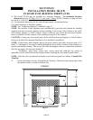
WALL
WALL
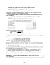
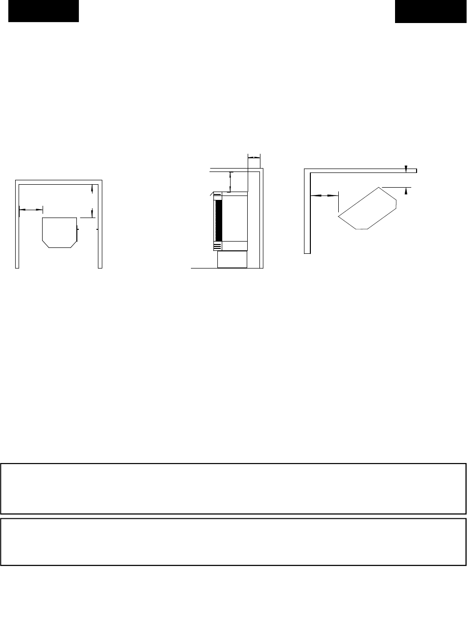
CORNER INSTALLATI
O
NOTE:
DIMENSIONS SHOWN ARE
MINIMUM CLEARANCE TO
COMBUSTIBLE WALL.
0"
7"
REAR WALL
STOVE
26"
Figure 10
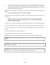
0"
CEILING
FACING UNIT
7"
REAR WALL
SIDE VIEW
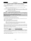
LEFT
WALL
RIGHT
WALL
7”
26"
SECTION VI
MODEL 384 (FS)
FREESTANDING INSTALLATION
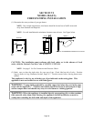
(1) Determine the exact position of your gas heater.
NOTE: Due to high temperatures, this heater should be located out of traffic areas and
away from furniture and draperies.
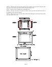
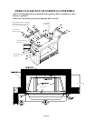
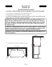
NOTE: For safe installation the minimum clearances must be met. See Figure below.
CAUTION: The installation must conform with local codes, or in the absence of local
codes, with the National Fuel Gas Code, ANSI Z223.1/NFPA54.
NOTE: See page 5 for Gas Connection and Pressure Check.
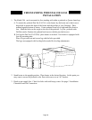
(2) Make sure you have the right valve for your type of gas. Check label on side of valve. Position
logs as shown in Log Placement Section, Pages 6-7. Position screen before leaving heater unat-
tended.
This appliance is only for use with the type of gas indicated on the rating plate. This
appliance is not convertible for use with other gases.
WAR N I N G: “Young children should be carefully supervised when they are in the same
room with the appliance.” “Children and adults should be alerted to the hazards of high
surface temperature and should stay away to avoid burns or clothing ignition
.”
WAR N I N G: When the appliance is installed directly on carpeting, tile or other combus-
tible material, other than wood flooring, the appliance shall be installed on a metal or
wood panel extending the full width and depth of the appliance.
2”
2”
2”
Page 28


