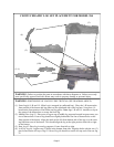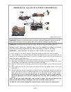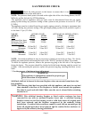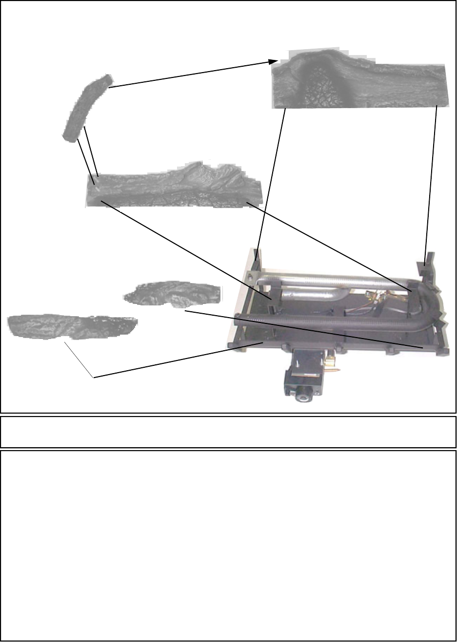
CR3329 CERAMIC LOG SET PLACEMENT FOR MODEL 384
(1-L)
(2)
(4)
(3)
WARNING: Failure to position the parts in accordance with these diagrams or failure to use only
parts specifically approved with this heater may result in property damage or personal injury.
(1) Front Log(s) #1-R and 1-L (Slim Log(s) wrapped in cardboard box) . Place the 1-R between the
front portion of the burner and log grates on the right hand side of the log base. Next place 1-L
between the front portion of the burner and log grates. Note: logs 1-R and 1-L should over lap in
the center of the burner base to create the front log.
(2) Middle Glow Log #2 . Place rear of log on top of middle log supports located in open center por-
tion of burner base. Front of log should rest slightly behind the rear line of burner holes on the
front portion of the burner. Align the notch on the left front bottom side of the log over the exist-
ing hold down nut of the burner. This should align the log at the right position from left or right
on the burner.
(3) Rear Log #3. Place log in rear log supports. Center from left to right.
(4) Left Top Log #4. Log has two (2) holes in the bottom front side. Align the holes with the two (2)
pins located on the left top of log #2. Rear of log #4 should rest on the left top end of the rear log
#3.
WARNING: POSITIONING OF LOGS IS VERY CRITICAL (SEE DIAGRAM ABOVE).
(1-R)
Page 6


