


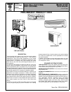
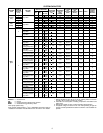

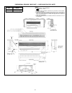
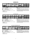
SPECIFICATIONS — 538S CONDENSING UNITS
UNIT 538S 024 048
NOMINAL CAPACITY (Tons) 24
OPERATING WEIGHT (lb) 159 292
REFRIGERANT TYPE R-22
Control (Cooling) TXV in Condensing Unit
Factory Charge (lb)*
Circuit A 5.0 5.5
Circuit B — 5.5
COMPRESSOR TYPE Copeland Scroll
Quantity...Model 1...ZR23K1 2...ZR23K1
Oil (Recharge) (oz) 25 25
OUTDOOR FAN Propeller, Direct Drive
Rpm 850 850
Nominal Air Cfm 1720 3900
OUTDOOR COIL Copper Tube, Aluminum Fin
Face Area (sq ft)...No. of Rows 6.1...2 12.3...2
Fins/in. 15 15
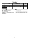
CONTROLS
High-Pressure (psig)
Cut-in 320±20
Cutout 426 ± 7
Low-Pressure (psig)
Cut-in 22±5
Cutout 7±3
Fusible Plug 210 F
Control Voltage 24
REFRIGERANT LINES
Connection Type Sweat
Vapor Supply Line Quantity...OD (in.) 2...
3
⁄
8
4...
3
⁄
8
Vapor Return Line Quantity...OD (in.) 2...
5
⁄
8
4...
5
⁄
8
Maximum Length (ft) 50 50
Maximum Lift (Fan Coil Above Outdoor) (ft) 30† 30†
Maximum Lift (Fan Coil Below Outdoor) (ft) 30† 30†
EXTERNAL FINISH Alpine Mist (Beige)
LEGEND
TXV — Thermostatic Expansion Valve
*Charges are preliminary estimates and are based on 25 ft of intercon-
necting line.
†Maximum system lift is 30 ft between lowest system component and
highest system component.
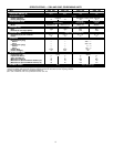
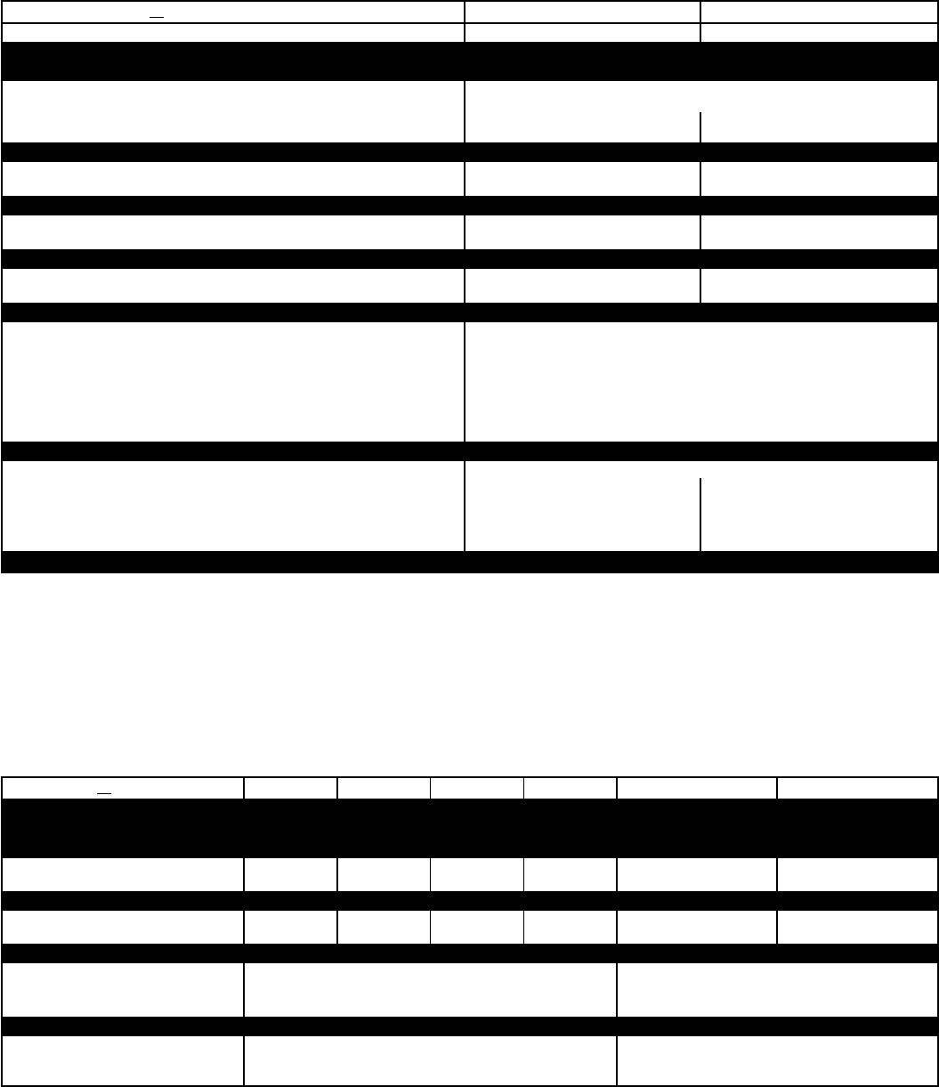
SPECIFICATIONS — 619E FAN COIL UNITS
UNIT 619E 009* 012* 009† 012† 018 024
OPERATING WEIGHT (lb) 18.7 24.2 18.7 24.2 39 43
REFRIGERANT** R-22 R-22 with AccuRaterா Control or TXV
FAN Centrifugal Blower
Rpm 1250 1150 1250 1150 1300 1505
Nominal Cfm (High Speed) 215 302 252 302 480/455** 550/525**
COIL
Face Area (sq ft)...Rows 1.45...2 1.60...3 1.45...2 1.60...3 2.56...2 2.56...3
Fins/in. 18 17 18 17 15.9 18.1
CONNECTIONS (MPT)
Vapor (in.) Flare
1
⁄
2
5
⁄
8
Liquid (in.) Flare
1
⁄
4
3
⁄
8
Condensate Drain
5
⁄
8
5
⁄
8
LINE SIZES
Vapor (in.)
1
⁄
2
5
⁄
8
Liquid (in.)
1
⁄
4
3
⁄
8
Condensate Drain
5
⁄
8
5
⁄
8
LEGEND
TXV — Thermostatic Expansion Valve (538S Systems Only)
*Cooling-only fan coil unit.
†Heat pump fan coil unit. Cooling only/Heat pump.
**See outdoor unit nameplate for correct system charge.
8