


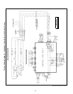
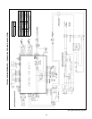

APPLICATION DATA (cont)
9. Metering devices
a. 009, 012 units — The 009 and 012 units have capillary
tubes for refrigerant metering located in the outdoor con-
densing unit.
b. 018, 024 units — The 018, 024 units use a piston-type
metering device located in the indoor unit.
NOTE: All 538A, 538C, 538D (018, 024) duct-free split sys-
tems use Chattleff style AccuRaterா pistons. DO NOT mix
piston types. All 538D009, 012 systems use Aeroquip type
pistons. See Long-Lines Applications section on page 20
for changes in piston sizes due to long lines.
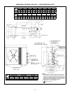
10. Drain connections
Install drains to meet local sanitation codes. If adequate
gravity drainage cannot be provided, unit should be
equipped with accessory condensate pump. High wall fan
coil unit condensate pumps have a 10 ft lift capability above
the condensate pan level.
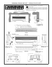
See base unit dimensional drawings on pages 13 and 14
for fan coil unit drain locations and sizes.
NOTE: High wall fan coil units have internal condensate
traps.
Drain connections may be routed through alternate loca-
tions on most fan coils. See base unit dimensional drawings
on pages 13 and 14 for possible alternate locations.
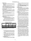
11. Refrigerant lines
a. General refrigerant line sizing:
1) All charges, line sizing, and capacities are based on
runs of 25 ft. For runs over 25 ft, consult long-lines
section on page 20 for proper line sizing, charge, and
AccuRater refrigerant metering device sizing.
NOTE: For runs less than 25 ft, some of the charge may
need to be removed to obtain the correct system super-
heat. The minimum line length should be 8 ft.
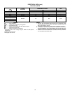
MAXIMUM LINE LENGTHS
UNIT
MAXIMUM
EQUIVALENT
FT
MAXIMUM LIFT— MAXIMUM LIFT—
FAN COIL
BELOW
FAN COIL
ABOVE
CONDENSING CONDENSING
UNIT UNIT
538A, 538D018,024 200 150 65
538D, 538D009 35 35 16
538C, 538D012 49 35 16*
538S 50 30† 30†
*This changes to 25 ft with addition of accessory crankcase heater.
†Maximum distance permitted is 30 ft from lowest system component to
highest system component.
2) Refrigerant lines should not be buried in the ground.
If it is necessary to bury the lines, not more than
36 in. should be buried. Provide a minimum 6-in. ver-
tical rise to the service valves to prevent refrigerant
migration.
3) The vapor line must be insulated. Use a minimum of
1
⁄
2
-in. thick insulation. Closed-cell insulation is rec-
ommended in all long-line (over 25 ft) applications.
4) Special consideration should be given to isolating
interconnecting tubing from the building structure.
Isolate the tubing so that vibration or noise is not
transmitted into the structure.
b. 538C,D009,012 units
1) These units are shipped with a charge of R-22 refrig-
erant. Check the charge using the superheat
method. Since all refrigerant lines are on the low side
of the system, it is not normally necessary to add or
remove charge.
2) These units have mixed-phase refrigerant flow in the
liquid line. DO NOT install a filter drier in the liquid
line. The liquid line must be insulated.
3) No line size changes should be made on 009, 012
units.
c. 538A,D018, 024 units
1) These units are shipped with a charge of R-22 refrig-
erant. See System Piston Guide and Refrigerant
Charges tables on page 21 for system charges. Add
additional charge by weight as necessary and check
the charge with a superheat calculator.
2) For these units, install the filter drier provided with
the unit in the liquid line. Use of a field-supplied mois-
ture indicator is also recommended.
d. 538S units
1) Outdoor units are shipped with the charges listed in
the Specifications — 538S Condensing Units table
on page 8. To determine if additional charge is re-
quired, add all charges listed in fan coil unit specifi-
cations table(s) in the Product Data literature for your
system (per circuit). The sum of the charges listed is
the system circuit charge required based on 25 ft of
line.
2) For the 538S units, filter driers are provided in the
unit.
3) Vapor supply lines on all 538S units should be
5
⁄
8
in.
only. DO NOT resize vapor supply lines for additional
length.
4) When sizing vapor return line, determine line length
by finding equivalent ft of tubing. Equivalent line
lengths equal the linear length (measured length) of
the interconnecting vapor return tubing plus losses
due to elbows (see Fitting Loss in Equivalent Ft For
Elbows table on page 21). If the number of elbows is
not yet known, assume 50% additional length for
equivalent length. In determining line size, be sure oil
can be properly returned to the compressor. Contact
your local representative for oil return recommenda-
tions as necessary. For line lengths from 25 to 50 ft,
no special tubing requirements are normally re-
quired. Adjust charge to required amount by adding
charge per subcooling method. Refer to 538S base
unit installation instructions for charging details.
e. Long-lines applications, 538A,D018,024 units:
1) Liquid lines on all 538A,D018,024 units should be
3
⁄
8
in. only. DO NOT resize liquid lines for additional
length.
2) When sizing vapor line, determine line length by find-
ing equivalent ft of pipe. Equivalent line lengths
equal the linear length (measured length) of the in-
terconnecting vapor tubing plus losses due to elbows
(see Fitting Loss in Equivalent Ft For Elbows table
on page 21). If the number of elbows is not yet
known, assume 50% additional length for equivalent
length. In determining line size, be sure oil can be
properly returned to the compressor. Consult your lo-
cal representative for proper oil return recommenda-
tions as necessary. For line lengths from 15 to 49 ft,
no special piping requirements are normally
required. Adjust charge to required amount by add-
ing charge per Step l) on page 23 and checking
superheat.
20