


APPLICATION DATA (cont)
e) Changes in piston size — The metering device for a
long-line application must be adjusted to compen-
sate for the frictional losses due to the long refriger-
ant lines, refrigerant lines accessories, and indoor
coil above or below the outdoor unit. The
AccuRaterா refrigerant metering device piston may
need to be changed to provide this adjustment. The
AccuRater piston should be changed for the indoor
unit depending upon system configuration and line
length. Use the Change in Indoor Unit Piston Size El-
evation table on next page to determine correct
AccuRater piston size. The standard piston size is
shown in the System Piston Guide and Refrigerant
Charges tables on page 21.
f) Horizontal configuration — If the total equivalent
horizontal length is 100 ft or longer, the indoor piston
must be increased one full piston size, in addition to
the charge change in Step l), page 23. If exact size is
not available, use next smaller size per Chattleff
Common Piston Sizes table.
g) Elevated configuration — After finding the appropri-
ate change in piston size, add or subtract the
change from the original piston size number. If the
piston size is decreased, round down to the next
common piston size. If the piston size is increased,
round the new piston size up to the next common
piston size.
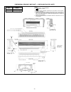
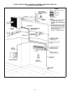
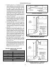
h) Liquid line solenoid and tubing configuration — The
solenoid has a flow arrow stamped on the valve
body. When the valve is closed (not energized), the
pressure is applied in the direction of the flow arrow,
complete shut off will occur. If pressure is applied
against the direction of the arrow, leakage through
the valve will occur. When determining the proper lo-
cation for a solenoid in a system liquid line, consider
both flow direction and location of the valve in the
system. See the diagram below for proper location,
and install per sections i), j), and k) below.
i) Horizontal configuration (see figure below) — Install a
biflow (538D only or standard) liquid line solenoid
valve within 2 ft of the fan coil with the flow arrow
pointing toward the indoor unit if equivalent ft of pip-
ing is 100 ft or more.
Slope the vapor line toward the indoor unit to provide
for refrigerant migration protection during the off cycle
due to temperature differences caused by slight el-
evation changes between indoor and outdoor units.
NOTE: When installing a liquid line solenoid, a low-
voltage transformer may be required.
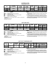
CHANGE IN INDOOR UNIT PISTON SIZE
FOR ELEVATION
OUTDOOR UNIT ABOVE INDOOR UNIT
Ft Piston Change
0- 25 0
26- 50 -3
51- 75 -5
76-100 -7
101-125 -9
126-150 -10
INDOOR UNIT ABOVE OUTDOOR UNIT
Ft Piston Change
0-25 0
26-65 +4
LEGEND
FCU — Fan Coil Unit
OU — Outdoor Unit
Horizontal Configuration
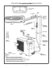
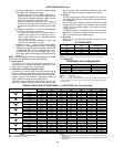
Lowered Configuration — Indoor Unit
Installed Below the Outdoor Unit
LEGEND
FCU — Fan Coil Unit
OU — Outdoor Unit
Liquid Line
Solenoid Valve
(if used)
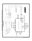
Elevated Configuration — Indoor Unit
Installed Above the Outdoor Unit
LEGEND
FCU — Fan Coil Unit
OU — Outdoor Unit
Liquid Line
Solenoid Valve
(Required over 25 ft)
*009,012 systems.
†538A,538D018,024 systems.
*009,012 systems.
†538A,538D018,024 systems.
*009,012 systems.
†538A,538D018,024 systems.
22