


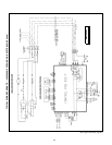
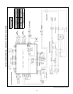
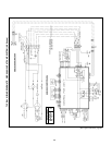
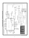

LEGEND AND NOTES FOR TYPICAL WIRING SCHEMATICS
OPERATING SEQUENCE
619E CONTROL SYSTEM — The 619E unit is equipped with a
microprocessor control which operates the system. This control
is located in the control box of the fan coil unit, with thermistors
located in the fan coil inlet and on the indoor coil. The 619E heat
pump fan coil units also have thermistors located on the outdoor
coil and in the outdoor air inlet. These thermistors monitor sys-
tem operation and control the operating mode. To change set-
tings or modes of operation, use the factory-supplied infrared
wireless remote controller. This controller allows the fan coil unit
to be operated from within the same room without any wire con-
nections to the unit.
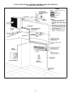
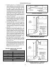
The remote controller includes a wall-mounted bracket. To in-
stall the bracket, attach bracket to the wall using factory-
supplied, double-sided tape. Install factory-supplied batteries
into the remote controller, and place the controller into the
bracket so that it will be ready for use.
OPERATING MODE MEMORY — After the system is turned off
or after a power failure, the system remains in the last operating
mode selected. When the system is turned back on, or when
power is automatically restored, operation continues in the
same operating mode as when power shut down.
AUTOMATIC OPERATION (AUTO.) MODE — If auto. mode is
selected, the system automatically switches the operating mode
from heating (heat pump system only) to cooling, or from cool-
ing to heating (heat pump system only) depending on the se-
lected temperature.
NOTE: Between the cooling cycle and the heating cycle there is
a neutral zone of approximately 2° F above and 2° F below the
selected temperature when only the fan is operating.
OPERATING FAULT DIAGNOSIS — The system includes an
automatic diagnosis feature which is activated under difficult or
unacceptable operating conditions. If such conditions occur, the
system stops automatically, the operating fault signal appears
(green ‘‘UNIT ON’’ light on the front of the fan coil unit flashes),
and an analysis of the system operating conditions is initiated.
The system will then be restarted automatically, as soon as nor-
mal conditions have been restored, or it will remain off. If the
system does not start again, the green ‘‘UNIT ON’’ light will flash
an error code.
MICROPROCESSOR CONTROL OPERATION — This system
is controlled by a microprocessor designed to give optimum lev-
els of comfort and operating efficiency. The control is located in
the 619E unit. To operate the unit, the factory-supplied remote
controller is required.
There are 8 (619E cooling-only systems) or 10 (619E heat
pump systems) operating modes (including the off mode) for the
unit. Each mode operates as follows:
• Off Mode — When the unit is in the off mode, all functions
(compressor, outdoor fan, indoor fan, and air sweep) are off,
except the reversing valve (619E heat pump units only),
which will stay energized if the unit was last operated in the
cooling mode.
• Air Circulation Mode (Fan Operation Only) — When air circu-
lation mode is selected, the indoor fan will operate continu-
ously in the selected speed (high, medium, low, or auto.). If
the auto. mode is selected, the indoor fan will operate at low
speed. The compressor and outdoor fan are off. The reversing
valve (619E heat pump units only) will remain in the last
operating mode.
• Cooling Mode — When the cooling mode is selected, the in-
door fan will operate continuously at the selected speed if the
speed is high, medium, or low. If the indoor fan is in auto.
mode, the fan will change operating speeds depending on the
difference between the room temperature and the set point.
The reversing valve (619E heat pump units only) will be on.
The compressor cannot run for 3 minutes from the time the
system starts up or for 3 minutes from the time the compres-
sor last operated. When the temperature of the room is equal
to or greater than the selected temperature, the compressor
and outdoor fan will operate until the room temperature is
2° F below the set point, and then shut off. When the room
temperature is less than the selected temperature, the com-
pressor and outdoor fan remain off.
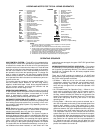
AGING — For Burn-In Test
(short terminals)
AS — Assembly
C—Contactor
CAP — Capacitor
CH — Crankcase Heater
CLO — Compressor Lockout
CN — Connector
COMP — Compressor
CT CLO — Current Sensing Loop (Lockout)
DFB — Defrost Board
DFT — Defrost Thermostat
EMI — Electromagnetic Interference
FMC — Fan Motor Capacitor
FU — Fuse
GND — Ground
HA — Home Automation
HPS — High-Pressure Switch
IDC TH — Indoor-Coil Thermistor
IDFM — Indoor-Fan Motor
JEM-A — Japan Electric Manufacturing
Industry Association
K—Relay
LLPS — Liquid Low Pressure Switch
LPS — Low-Pressure Switch
ODA TH — Outdoor-Air Thermistor
ODC TH — Outdoor-Coil Thermistor
OFM — Outdoor-Fan Motor
OFR — Outdoor-Fan Relay
OL — Overload
PCB — Printed Circuit Board
PTC — Start Thermistor
RA TH — Return-Air Thermistor
RC — Resistor Capacitor
RCV — Receiver
RVS — Reversing Valve Solenoid
SC — Start Capacitor
SR — Start Relay
STM — Step Motor
TB — Terminal Block
TP — Thermal Protector
TRAN — Transformer
Terminal (Marked)
Terminal (Unmarked)
Splice
Terminal Block
Factory Wiring
Field Control Wiring
Field Power Wiring
Accessory or Optional Wiring
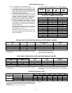
NOTES:
1. If any of the original wire furnished must be replaced, it must be replaced
with type 90 C wire or its equivalent.
2. Wire in accordance with National Electrical Code (NEC) and local codes.
3. The CLO locks out the compressor to prevent short cycling on compressor
overloads and safetydevices. Before replacing CLO,check these other de-
vices. A minimum 1 amp turn is required to hold contacts closed.
4. A thermistor wiring cable is provided with the fan coil unit.
5. Compressor and fan motors are protected by internal thermal overloads.
6. Transformer has an internal 2 amp thermal fuse on the primary side.
LEGEND
28