


APPLICATION DATA (cont)
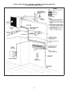
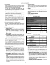
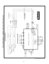
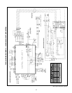
j) Elevated configuration — Indoor unit installed above
the outdoor unit (see figure at right):
• If there is over 25 ft of lift, a biflow (538D only) or
standard solenoid valve is required in the liquid line.
• The maximum elevation difference is 65 ft, and the
maximum equivalent ft of piping is 200.
• Install an inverted trap in the vapor line. The top of
the trap must be above the top of the fan coil. This
prevents the refrigerant from collecting in the vapor
line.
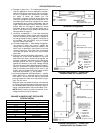
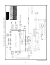
k) Lowered configuration — Indoor unit installed below
the outdoor unit (see figure at right):
• For lines shorter than 100 ft, no solenoid valve is
required in the liquid line. For lines over 100 ft, in-
stall a biflow (538D only) or standard solenoid
valve in the liquid line.
• The maximum elevation difference is 150 ft, and
the maximum equivalent ft is 200.
l) Additional charge — The unit should be charged by
weighing in the appropriate charge. Add charge
based on the actual length of line which is over 25 ft
of liquid line. Add .58 oz of refrigerant per 1 ft in-
crease over the 25 ft line to the charge listed in Sys-
tem Piston Guide and Refrigerant Charges table on
page 21.
NOTE: This only applies to systems where the piston is located
at the indoor unit (538A018,024 and 538D018,024).
12. Group control
The 619E fan coil units may be group controlled from a
single timeclock or energy management system by inter-
rupting the 24-v power to the control board.
13. Thermistors (Heat Pump Systems Only)
Thermistors are used on both indoor and outdoor units to
determine operating conditions. Proper thermistor location
is critical to unit operation. All thermistors have identical re-
sistance values. See Thermistor Equivalence charts on
typical system wiring schematics (pages 24-27).
Thermistor cable assemblies are provided with fan coil
units to run between indoor and outdoor units. High-voltage
and thermistor cable assemblies should not touch each
other, and cable runs may be extended up to 200 ft.
14. Wiring
Use only copper wires from the disconnect to the unit ter-
minal block.Aluminum and copper-clad aluminum wires are
not acceptable.
All duct-free split systems (except the 009,012 outdoor
units) provide 24-v power for the outdoor unit in the duct-
free fan coil. The 009,012 outdoor units systems use high-
voltage controls.
The 009,012 outdoor units system fan coil units must have
power wires run from the outdoor condensing unit to the in-
door unit to prevent out-of-phase wiring.
15. Air throw
Refer to Air Throw Data table below for system air throw
capabilities.
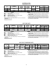
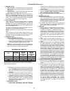
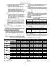
AIR THROW DATA*
FAN COIL
SIZE
HIGH SPEED
CFM
APPROXIMATE
AIR THROW (FT)
009 215/252* 16
012 302 24
018 480/455* 30
024 550/525* 35
*Cooling only unit/Heat pump unit.
NOTE: Air throw is with unit mounted with typical clearances in a 10-ft high room.
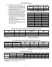
16. Sound data
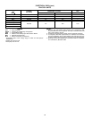
CONDENSING UNIT SOUND RATINGS
UNIT SIZE SOUND RATING (Decibels) FREE FIELD dBA*
009 66 55.7
012 66 55.7
018 68 57.7
024 68 57.7
LEGEND
Decibels — Sound levels
dBA — Decibels on the A Scale
*Free field is a rating with no reflective surfaces near the unit. Data sound pressure is
measured at 3.2 ft (1 m) from the unit. See Sound Power Data Octave Bands table for
more information.
SOUND POWER DATA OCTAVE BANDS — A WEIGHTED (Fan Coil Units Only)
UNIT FAN SPEED
OCTAVE BAND DATA (dBA)
125 250 500 1000 2000 4000 8000
619F 009
Cooling
Only
High 36.5 40.3 45.2 48.2 42.3 33.2 31.2
Medium 32.8 37.9 43.6 44.9 39.1 29.8 31.2
Low 31.7 36.6 41.6 41.6 35.4 27.7 31.2
619F 009
Heat
Pump
High 38.2 41.1 46.2 47.9 43.0 33.6 31.2
Medium 31.7 39.8 45.0 45.3 42.0 36.8 36.8
Low 29.2 38.4 43.9 41.9 38.6 28.1 31.2
619F 012
Cooling
Only
High 36.7 43.5 50.2 51.1 46.5 38.6 31.7
Medium 33.6 42.5 47.1 48.8 43.4 36.2 33.4
Low 33.5 41.6 43.8 45.6 39.8 33.0 32.7
619F 012
Heat
Pump
High 35.1 43.8 50.3 51.1 46.4 38.0 31.2
Medium 31.7 43.3 46.3 48.6 42.9 34.2 31.2
Low 29.1 42.2 42.9 45.6 39.1 30.3 31.2
619F 018
Cooling
Only
High 40.8 49.1 53.7 55.2 49.1 41.3 32.3
Medium 38.0 46.7 50.6 51.7 44.9 35.8 31.6
Low 37.3 44.4 47.5 48.6 40.4 32.0 31.6
619F 018
Heat
Pump
High 37.0 44.4 49.3 50.4 43.4 35.6 31.9
Medium 39.8 46.9 52.2 53.7 47.4 40.1 32.7
Low 43.2 49.1 54.0 56.0 50.7 44.0 34.0
619F 024
Cooling
Only
High 44.9 51.9 59.1 59.5 54.8 48.0 36.7
Medium 43.7 50.5 57.2 57.0 51.8 44.4 33.6
Low 40.7 47.7 55.1 54.7 49.0 40.5 32.2
619F 024
Heat
Pump
High 43.8 51.5 58.5 58.8 53.5 46.2 36.0
Medium 41.4 49.5 56.5 56.2 50.4 42.5 36.0
Low 38.9 47.3 54.4 53.7 47.4 39.0 36.0
LEGEND
ARI — Air Conditioning & Refrigeration Institute
dBA — Decibels on the A scale
NOTES:
1. Outdoor sound levels are tone corrected values taken inaccordance with ARI Sound
Standard 270.
2. Indoor sound levels are tone corrected values taken in accordance with ARI Sound
Standard 350.
23