


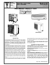

The indoor units include protection against freeze-up (heat
pumps), high discharge temperature, and self diagnostics to en-
sure reliability.
RESTART FUNCTION FOR AUTOMATIC START AFTER A
POWER FAILURE eliminates the need to reset the unit after a
power failure. The unit restarts in the same mode that was op-
erating prior to the power failure and retains the selected set
point as well.
AUTOMATIC AIR SWEEP ensures evenly-distributed air within
the conditioned space for ultimate comfort. The air sweep fea-
ture sweeps the air from side to side.
WEATHER-PROTECTED CABINET is protected with a heavy,
galvanized steel coating, then coated again with a layer of zinc
phosphate to which a coat of polyester powder is applied and
baked on. This provides each unit with a hard, smooth finish that
will last for many years.
All screws on the cabinet exterior are coated for long-lasting,
rust-resistant, quality appearance.
TOTALLY ENCLOSED FAN MOTOR means greater reliability
under rain conditions and dependable performance for many
years. Permanent-split-capacitor-type motors provide the most
economical operation.
REFRIGERANT SYSTEM is designed to provide dependability.
Each unit leaves the factory with a refrigerant charge. Additional
charge may be necessary depending on the application. Refrig-
erant service connections make checking operating pressures
easier. For precise refrigerant control, all 538A, 538C, and 538D
fan coil units feature an AccuRaterா piston in the fan coil unit,
and 009,012 units feature a capillary in the outdoor unit.
FIELD-INSTALLED ACCESSORY
DESCRIPTION AND USAGE
Condensate Pump — The pump provides condensate lift ca-
pability, and is an accessory for the fan coil units.
SUGGESTED USE:
• The condensate pump accessory is recommended when ad-
equate drain line pitch cannot be provided.
Winter Start Control (538A, 538S) — This condensing unit ac-
cessory is a single-pole, single-throw delay relay which by-
passes the low-pressure switch for approximately 3 minutes to
permit start-up for cooling operation under low load conditions
at low-ambient temperatures.
SUGGESTED USES:
• Applications where low-ambient cooling is required below
40 F outdoor-air temperature.
Wall mount kit — The kit includes brackets to be mounted to
the outside of the structure to raise unit from ground level, or to
mount the unit on a wall adjacent to a sloping roof. The wall
mount kit is also useful in areas of heavy snowfall or where
space is at a premium. The wall mount kit may be used with any
outdoor unit.
SUGGESTED USE:
• When application requires that outdoor unit be installed above
ground level.
Liquid solenoid valve (sizes 018 and larger) — The valve is
an electrically operated shutoff valve to be installed at the out-
door unit, and closes and opens in response to compressor op-
eration. The valve maintains a column of refrigerant in the liquid
line between compressor operation cycles and is required for
certain long-line applications. The valve should be used with all
long-line applications (over 100 ft).
SUGGESTED USE:
• Whenever long-line applications are used.
Low-Ambient Temperature Controls (down to −20 F) (538A,
538C, 538D) — The low-ambient kit is a solid-state head pres-
sure controller designed to control outdoor fan cycling, and is
activated by a pressure sensor. It is specifically designed to con-
trol fan-motor cycles in response to saturated condensing pres-
sure. This device maintains a constant saturated condensing
temperature of 100F±10Fatoutdoor-air temperatures be-
tween 55 F and −20 F, and may be used on all 538A, 538C, and
538D outdoor units without changing the outdoor-fan motor.
SUGGESTED USE:
• Applications where a significant amount of unit cooling opera-
tion is necessary at outdoor-air temperatures below 55 F.
Crankcase Heater — Crankcase heaters are only an acces-
sory for those units with scroll compressor(s). Heaters are
standard on units with reciprocating compressors.
SUGGESTED USE:
• Scroll compressor applications where an accessory low-
ambient kit has been installed.
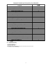
CONTENTS
Page
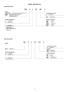
Model Description ...........................4
System Capacities...........................5
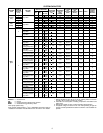
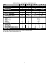
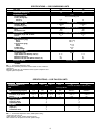
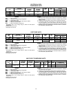
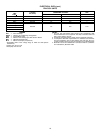
Specifications .............................6-8
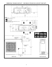
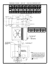
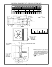
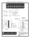
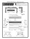
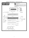
Dimensional Drawings .......................9-14
Electrical Data ............................15,16
Typical Installation ..........................17,18
Application Data ..........................19-23
Typical Wiring Schematics ....................24-27
Operating Sequence ........................28-30
Engineers’ Specification Guide .................31,32
2