


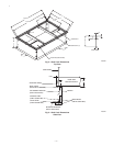

A. Adhere to the following criteria when selecting,
sizing, and installing the duct system:
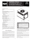
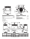
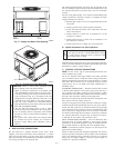
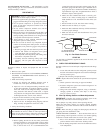
1. Units are shipped for side shot installation.
2. Select and size ductwork, supply-air registers, and return-air
grilles according to American Society of Heating, Refrig-
eration and Air Conditioning Engineers (ASHRAE) recom-
mendations.
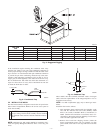
3. Use flexible transition between rigid ductwork and unit to
prevent transmission of vibration. The transition may be
screwed or bolted to duct flanges. Use suitable gaskets to
ensure weather tight and airtight seal.
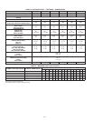
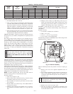
4. All units must have field-supplied filters or accessory filter
rack installed in the return-air side of the unit. Recom-
mended sizes for filters are shown in Tables 2 and 3.
5. Size all ductwork for maximum required airflow (either
heating or cooling) for unit being installed. Avoid abrupt
duct size increases or decreases or performance may be
affected.
6. Adequately insulate and weatherproof all ductwork located
outdoors. Insulate ducts passing through unconditioned
space, and use vapor barrier in accordance with latest issue
of Sheet Metal and Air Conditioning Contractors National
Association (SMACNA) and Air Conditioning Contractors
of America (ACCA) minimum installation standards for
heating and air conditioning systems. Secure all ducts to
building structure.
7. Flash, weatherproof, and vibration-isolate all openings in
building structure in accordance with local codes and good
building practices.
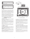
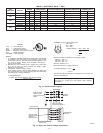
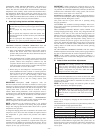
X. INSTALL ELECTRICAL CONNECTIONS
WARNING: The unit cabinet must have an uninter-
rupted, unbroken electrical ground to minimize the pos-
sibility of serious injury if an electrical fault should occur.
This ground may consist of an electrical wire connected
to the unit ground lug in the control compartment, or
conduit approved for electrical ground when installed in
accordance with NEC (National Electrical Code) ANSI/
NFPA 70 (latest edition) (in Canada, Canadian Electrical
Code CSA (Canadian Standards Association) C22.1) and
local electrical codes. Do not use gas piping as an
electrical ground. Failure to adhere to this warning could
result in serious injury or death.
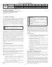
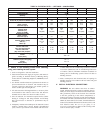
TABLE 2—PHYSICAL DATA — UNIT 583B — 030040-042090
UNIT SIZE 583B 030040 030060 036060 036090 042060 042090
NOMINAL CAPACITY (ton) 21/2 21/2 3 3 31/2 31/2
OPERATING WEIGHT (lb) 313 313 321 321 382 382
COMPRESSORS
Quantity
Scroll
1
REFRIGERANT (R-410A) Qty (lb) 5.5 5.5 6.9 6.9 9.0 9.0
REFRIGERANT METERING DEVICE
Orifice ID (in.)Check-Flo-Rater® Piston
.057 .057 .065 .065 .070 .070
CONDENSER COIL
Rows...Fins/in.
Face Area (sq ft)
1/17
12.7
1/17
12.7
2/17
9.1
2/17
9.1
2/17
12.3
2/17
12.3
CONDENSER FAN
Nominal CFM
Diameter (in.)
Motor Hp (RPM)
2350
22
1/8 (825)
2350
22
1/8 (825)
2350
22
1/8 (825)
2350
22
1/8 (825)
2350
22
1/8 (825)
2350
22
1/8 (825)
EVAPORATOR COIL
Rows...Fins/in.
Face Area (sq ft)
3/15
3.7
3/15
3.7
3/15
3.7
3/15
3.7
3/15
4.7
3/15
4.7
EVAPORATOR BLOWER
Nominal Airflow (CFM)
Size (in.)
Motor Hp
800
10x10
1/4
1000
10x10
1/4
1200
10x10
1/2
1200
10x10
1/2
1400
11x10
3/4
1400
11x10
3/4
FURNACE SECTION*
Burner Orifice No.
(Qty...Drill Size) Natural
Burner Orifice No.
(Qty...Drill Size) Propane
2...44
2...50
2...38
2...46
2...38
2...46
3...38
3...46
2...38
2...46
3...38
3...46
HIGH-PRESSURE SWITCH (psig)
Cutout
Reset (Auto.)
610 ± 15
420 ± 25
LOSS-OF-CHARGE/LOW-PRESSURE
SWITCH (Liquid Line) (psig)
Cutout
Reset (Auto.)
20 ± 5
45 ± 10
RETURN-AIR FILTERS (in.)Throwaway 20 x 24x1 20 x 24x1 20 x 24x1 20 x 24x1 24 x 30x1 24 x 30x1
—9—