


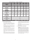
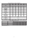
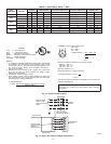
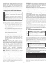
TABLE 5—ELECTRICAL DATA — 583B
UNIT
SIZE 583B
V-PH-HZ
VOLTAGE
RANGE
COMPRESSOR OUTDOOR FAN MOTOR INDOOR FAN MOTOR POWER SUPPLY
Min Max RLA LRA FLA FLA MCA MOCP*
030 208/230-3-60 187 253 9.6 63.0 0.8 2.1 14.9 20
036
208/230-3-60 187 253 12.2 77.0 0.8 3.6 19.7 30
460-3-60 414 506 5.1 35.0 0.8 1.9 9.1 15
042
208/230-3-60 187 253 13.5 77.0 1.6 4.1 22.6 35
460-3-60 414 506 6.3 39.0 0.9 2.0 10.8 15
048
208/230-3-60 187 253 14.7 91.0 1.6 4.1 24.1 35
460-3-60 414 506 6.5 46.0 0.9 2.0 11.0 15
060
208/230-3-60 187 253 18.1 137.0 1.6 6.2 30.4 45
460-3-60 414 506 9.0 62.0 0.9 3.2 15.4 20
452=5v
457=7v
455=2v
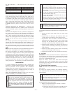
LEGEND
FLA — Full Load Amps
LRA — Locked Rotor Amps
MCA — Minimum Circuit Amps
MOCP — Maximum Overcurrent Protection
RLA — Rated Load Amps
NOTES:
1. In compliance with NEC (National Electrical Code) requirements
for multimotor and combination load equipment (refer to NEC
Articles 430 and 440), the overcurrent protective device for the
unit shall be Power Supply fuse. Canadian units may be
fuse or circuit breaker.
2. Minimum wire size is based on 60 C copper wire. If other than
60 C wire is used, or if length exceeds wire length in table,
determine size from NEC.
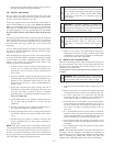
3. Unbalanced 3-Phase Supply Voltage
Never operate a motor where a phase imbalance in supply volt-
age is greater than 2%.
Use the following formula to determine
the percentage of voltage imbalance.
% Voltage imbalance
max voltage deviation from average voltage
= 100 x
average voltage
EXAMPLE: Supply voltage is 460-3-60.
AB = 452 v
BC = 464 v
AC = 455 v
452 + 464 + 455
Average Voltage =
3
1371
=
3
= 457
Determine maximum deviation from average voltage.
(AB) 457
(BC) 464
(AC) 457
Maximum deviation is 7 v.
Determine percent of voltage imbalance.
7
% Voltage Imbalance = 100 x
457
= 1.53%
This amount of phase imbalance is satisfactory as it is below the
maximum allowable 2%.
IMPORTANT: If the supply voltage phase imbalance is
more than 2%, contact your local electric utility company
immediately.
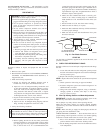
®
CKT BKR
—
Circuit Breaker
C99024
Fig. 13—Electrical Data Legend
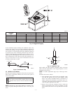
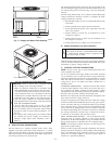
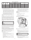
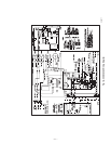
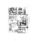
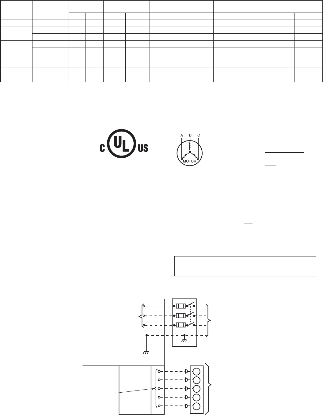
Fig. 14—High- and Control-Voltage Connections
C99018
POWER
SUPPLY
FIELD-SUPPLIED
FUSED DISCONNECT
HIGH VOLTAGE
POWER LEADS
(SEE UNIT WIRING
LABEL)
GND
CONTROL BOX
SPLICE BOX
LOW-VOLTAGE
POWER LEADS
(SEE UNIT
WIRING LABEL)
W
Y
G
R
C
WHT(W1)
YEL(Y)
GRN(G)
RED(R)
BRN(C)
THERMOSTAT
(TYPICAL)
—12—