


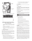
1. Remove the combustion blower wheel and motor assembly
according to directions in Combustion-Air Blower section
below.
2. Remove the 3 screws holding the blower housing to the flue
collector box cover (see Fig. 25).
3. Remove the 12 screws holding the flue collector box cover
(Fig. 25) to the heat exchanger assembly. Inspect the heat
exchangers.
4. Clean all surfaces as required, using the wire brush.
D. Combustion-Air Blower
Clean periodically to assure proper airflow and heating efficiency.
Inspect blower wheel every fall and periodically during heating
season. For the first heating season, inspect blower wheel bi-
monthly to determine proper cleaning frequency.
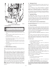
To inspect blower wheel, remove draft hood assembly. Shine a
flashlight into opening to inspect wheel. If cleaning is required,
remove motor and wheel as follows:
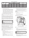
1. Remove unit access panel (See Fig. 24).
2. Remove the 7 screws that attach induced-draft motor
mounting plate to blower housing (See Fig. 25).
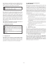
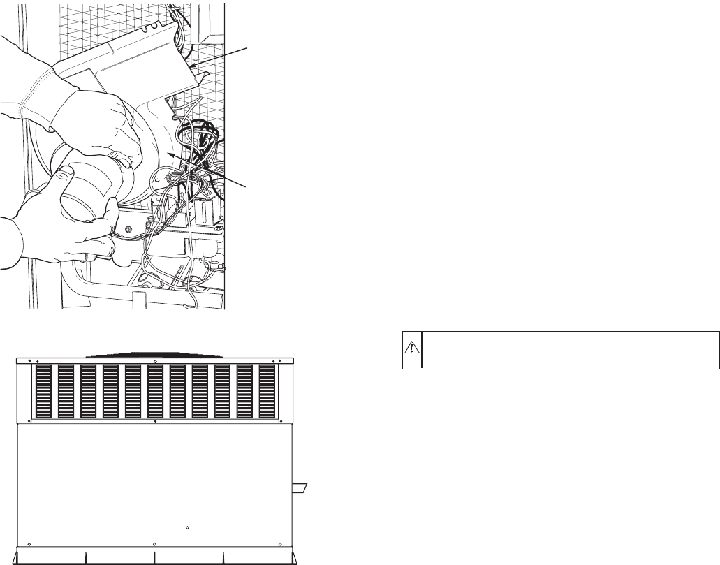
3. Slide the motor and blower wheel assembly out of the
blower housing (See Fig. 26). Clean the blower wheel. If
additional cleaning is required, continue with Steps 4 and 5.
4. To remove blower, remove 2 setscrews (See Fig. 26).
5. To remove motor and cooling fan assembly, remove 4
screws that hold blower housing to mounting plate.
6. To reinstall, reverse the procedure outlined above.
E. Limit Switch
Remove unit access panel. Limit switch is located on the blower
partition.
F. Burner Ignition
Unit is equipped with a direct spark ignition 100% lockout system.
Ignition module is located in the control box. Module contains a
self-diagnostic LED. During servicing, refer to label diagram for
LED interpretations.
If lockout occurs, unit may be reset by either momentarily
interrupting power supply to unit, or turning selector switch to
OFF position at the thermostat.
G. Main Burners
At the beginning of each heating season, inspect for deterioration
or blockage due to corrosion or other causes. Observe the main
burner flames and adjust if necessary.
CAUTION: When servicing gas train, do not hit or plug
orifice spuds.
REMOVAL OF GAS TRAIN
1. Shut off manual gas valve.
2. Shut off power to unit.
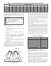
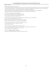
3. Remove unit access panel (See Fig. 27).
4. Disconnect gas piping at unit gas valve.
5. Remove wires connected to gas valve. Mark each wire.
6. Remove ignitor and sensor wires at the ignitor module.
7. Remove the mounting screw that attaches the burner rack to
the basepan (See Fig. 25).
8. Slide the burner rack out of the unit (See Figs. 25 and 28).
9. To reinstall, reverse the procedure outlined above.
H. Condenser Coil, Evaporator Coil, and Condensate
Drain Pan
Inspect the condenser coil, evaporator coil, and condensate drain
pan at least once each year.
The coils are easily cleaned when dry; therefore, inspect and clean
the coils either before or after each cooling season. Remove all
obstructions, including weeds and shrubs, that interfere with the
airflow through the condenser coil.
Straighten bent fins with a fin comb. If coated with dirt or lint,
clean the coils with a vacuum cleaner, using the soft brush
attachment. Be careful not to bend the fins. If coated with oil or
grease, clean the coils with a mild detergent-and-water solution.
Rinse coils with clear water, using a garden hose. Be careful not to
splash water on motors, insulation, wiring, or air filter(s). For best
results, spray condenser coil fins from inside to outside the unit.
On units with an outer and inner condenser coil, be sure to clean
between the coils. Be sure to flush all dirt and debris from the unit
base.
Inspect the drain pan and condensate drain line when inspecting
the coils. Clean the drain pan and condensate drain by removing all
foreign matter from the pan. Flush the pan and drain tube with
clear water. Do not splash water on the insulation, motor, wiring,
or air filter(s). If the drain tube is restricted, clear it with a
‘‘plumbers snake’’ or similar probe device. Ensure that the
auxiliary drain port above the drain tube is also clear.
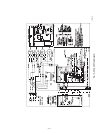
Fig. 26—Removal of Motor and Blower Wheel
C99085
BLOWER
HOUSING
2 SETSCREWS
(HIDDEN)
Fig. 27—Unit Access Panel
C99090
—22—