


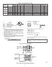
AUXILIARY LIMIT SWITCH (ROLLOUT)—The function of
the switch is to close the main gas valve in the event of flame
rollout. The switch is located above the main burners. When the
temperature at the auxiliary switch reaches the maximum allow-
able temperature, the R control circuit trips, closing the gas valve
and stopping gas flow to the burners. The indoor (evaporator) fan
motor (IFM) and induced draft motor continue to run until switch
is reset. The IGC LED will display FAULT CODE 7.
C. Start-Up Cooling Section and Make Adjustments
CAUTION: Complete the required procedures given in
the Pre-Start-Up section on previous pages before starting
the unit.
Do not jumper any safety devices when operating the
unit.
Do not operate the compressor when the outdoor tem-
perature is below 40° F (unless accessory low-ambient kit
is installed).
Do not rapid-cycle the compressor. Allow 5 minutes
between "on" cycles to prevent compressor damage.
CHECKING COOLING CONTROL OPERATION—Start and
check the unit for proper cooling control operation as follows:
1. Place room thermostat SYSTEM switch in OFF position.
Observe that blower motor starts when FAN switch is
placed in ON position and shuts down when FAN switch is
placed in AUTO position.
2. Place SYSTEM switch in COOL position and FAN switch
in AUTO position. Set cooling control below room tem-
perature. Observe that compressor, condenser fan, and
evaporator blower motors start. Observe that cooling cycle
shuts down when control setting is satisfied. The evaporator
fan will continue to run for 30 seconds.
3. When using an auto-changeover room thermostat, place
both SYSTEM and FAN switches in AUTO positions.
Observe that unit operates in Heating mode when tempera-
ture control is set to "call for heating" (above room
temperature) and operates in Cooling mode when tempera-
ture control is set to "call for cooling" (below room
temperature).
IMPORTANT: Three-phase, scroll compressor units are
direction-oriented. These units must be checked to ensure proper
compressor 3-phase power lead orientation. If not corrected within
5 minutes, the internal protector will shut off the compressor. The
3-phase power leads to the unit must be reversed to correct
rotation. When turning backwards, scroll compressors emit el-
evated noise levels, and the difference between compressor suction
and discharge pressures may be dramatically lower than normal.
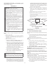
CHECKING AND ADJUSTING REFRIGERANT
CHARGE—The refrigerant system is fully charged with R-410A
(Puron) refrigerant, and is tested and factory sealed.
NOTE: Adjustment of the refrigerant charge is not required
unless the unit is suspected of not having the proper R-410A
charge. The charging label and the tables shown refer to system
temperatures and pressures.
A refrigerant charging chart label is attached to the outside of the
compressor access door. The chart includes the required suction
line temperature at given suction line pressures and outdoor
ambients..
An accurate superheat, thermocouple- or thermistor-type ther-
mometer, and a gauge manifold are required when using the
superheat charging method for evaluating the unit charge. Do not
use mercury or small dial-type thermometers because they are not
adequate for this type of measurement.
IMPORTANT: When evaluating the refrigerant charge, an indi-
cated adjustment to the specified factory charge must always be
very minimal. If a substantial adjustment is indicated, an abnormal
condition exists somewhere in the cooling system, such as insuf-
ficient airflow across either coil or both coils.
REFRIGERANT CHARGE—The amount of refrigerant charge is
listed on the unit nameplate. Refer to Bryant Refrigeration Service
Techniques Manual, Refrigerants section.
Unit panels must be in place when unit is operating during
charging procedures.
NO CHARGE: Use standard evacuating techniques. After evacu-
ating system, weigh in the specified amount of refrigerant (refer to
system data plate).
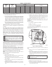
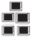
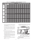
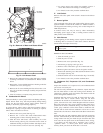
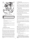
LOW CHARGE COOLING: Measure outdoor ambient using
Cooling Charging Charts (Figs. 20-24). Vary refrigerant until the
conditions of the chart are met. Note that charging charts are
different from type normally used. Charts are based on charging
the units to correct superheat for the various operating conditions.
Accurate pressure gauge and temperature sensing devices are
required. Connect the pressure gauge to the service port on the
suction line. Mount the temperature sensing device on the suction
line and insulate it so that the outdoor ambient does not effect the
reading. Indoor air CFM must be within the normal operating
range of the unit.
TO USE COOLING CHARGING CHARTS: Take the outdoor
ambient temperature and read the suction pressure gauge. Refer to
the chart to determine what the suction temperature should be.
NOTE: If the problem causing the inaccurate readings is a
refrigerant leak, refer to Check for Refrigerant Leaks section in
this document.
D. Indoor Airflow and Airflow Adjustments
CAUTION: For cooling operation, the recommended
airflow is 350 to 450 cfm for each 12,000 Btuh of rated
cooling capacity. For heating operation, the airflow must
produce a temperature rise that falls within the range
stamped on the unit rating plate.
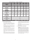
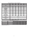
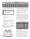
Table 7 shows the temperature rise at various air-flow rates. Table
9 shows both heating and cooling airflows at various external static
pressures. Refer to these tables to determine the airflow for the
system being installed.
NOTE: Be sure that all supply- and return-air grilles are open,
free from obstructions, and adjusted properly.
WARNING: Shut off gas supply then disconnect elec-
trical power to the unit before changing blower speed.
Electrical shock or explosion could cause serious injury
or death.
Airflow can be changed by changing the lead connections of the
blower motor.
All 583B units are factory wired for low speed and may need to be
wired for medium or high speed in the field.
For 208/230-v — The motor leads are color-coded as follows:
3-SPEED 2-SPEED
black = high speed black = high speed
blue = medium speed ---
red = low speed red = low speed
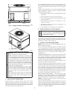
To change the speed of the blower motor (BM), remove the fan
motor speed leg lead from the blower relay (BR). This wire is
attached to terminal BM for single-phase and 3-phase units. To
change the speed, remove and replace with lead for desired blower
motor speed. Insulate the removed lead to avoid contact with
chassis parts.
—16—