


I. Condenser Fan
CAUTION: Keep the condenser fan free from all ob-
structions to ensure proper cooling operation. Never place
articles on top of the unit. Damage to unit may result.
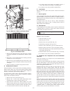
1. Remove 6 screws holding condenser grille and motor to top
cover.
2. Turn motor/grille assembly upside down on top cover to
expose the fan blade.
3. Inspect the fan blades for cracks or bends.
4. If fan needs to be removed, loosen the setscrew and slide
the fan off the motor shaft.
5. When replacing fan blade, position blade so that the hub is
1/8 in. away from the motor end (1/8 in. of motor shaft will
be visible).
6. Ensure that setscrew engages the flat area on the motor shaft
when tightening.
7. Replace grille.
J. Electrical Controls and Wiring
Inspect and check the electrical controls and wiring annually. Be
sure to turn off the gas supply, and then the electrical power to the
unit.
Remove access panel to locate all the electrical controls and
wiring. Check all electrical connections for tightness. Tighten all
screw connections. If any smokey or burned connections are
noticed, disassemble the connection, clean all the parts, restrip the
wire end and reassemble the connection properly and securely.
After inspecting the electrical controls and wiring, replace the
access panel. Start the unit, and observe at least one complete
heating cycle and one complete cooling cycle to ensure proper
operation. If discrepancies are observed in either or both operating
cycles, or if a suspected malfunction has occurred, check each
electrical component with the proper electrical instrumentation.
Refer to the unit wiring label when making these checkouts.
NOTE: Refer to the heating and/or cooling sequence of operation
in this publication as an aid in determining proper control
operation.
K. Refrigerant Circuit
Inspect all refrigerant tubing connections and the unit base for oil
accumulations annually. Detecting oil generally indicates a refrig-
erant leak.
If oil is detected or if low cooling performance is suspected,
leak-test all refrigerant tubing using an electronic leak-detector,
halide torch, or liquid-soap solution. If a refrigerant leak is
detected, refer to Check for Refrigerant Leaks section on page 13.
If no refrigerant leaks are found and low cooling performance is
suspected, refer to Checking and Adjusting Refrigerant Charge
section in this document.
L. Evaporator Airflow
The heating and/or cooling air-flow does not require checking
unless improper performance is suspected. If a problem exists, be
sure that all supply- and return-air grilles are open and free from
obstructions, and that the air filter is clean. When necessary, refer
to Indoor Airflow and Airflow Adjustments section in this docu-
ment to check the system airflow.
M. Metering Device–Check-Flo-Rater® Piston
This metering device is a fixed orifice and is contained in the brass
hex-body in the liquid line.
N. Pressure Switches
Pressure switches are protective devices wired into control circuit
(low voltage). They shut off compressor if abnormally high or low
pressures are present in the refrigeration circuit. These pressure
switches are specifically designed to operate with Puron (R-410A)
systems. R-22 pressure switches must not be used as replacements
for the Puron (R-410A) air conditioner.
LOSS OF CHARGE/LOW-PRESSURE SWITCH (air conditioner
only)
This switch is located on the liquid line and protects against low
suction pressures caused by such events as loss of charge, low
airflow across indoor coil, dirty filters, etc. It opens on a pressure
drop at about 20 psig. If system pressure is above this, switch
should be closed.
To check switch:
1. Turn off gas and then all power to unit.
2. Disconnect leads on switch.
3. Apply ohmmeter leads across switch. You should have
continuity on a good switch.
NOTE: Because these switches are attached to refrigeration
system under pressure, it is not advisable to remove this device for
troubleshooting unless you are reasonably certain that a problem
exists. If switch must be removed, remove and recover all system
charge so that pressure gauges read 0 psi. Never open system
without breaking vacuum with dry nitrogen.
HIGH-PRESSURE SWITCH—The high-pressure switch is lo-
cated in the discharge line and protects against excessive con-
denser coil pressure. It opens at 610 psig.
High pressure may be caused by a dirty condenser coil, failed fan
motor, or condenser air recirculation.
To check switch:
1. Turn off gas and then all power to unit.
2. Disconnect leads on switch.
3. Apply ohmmeter leads across switch. You should have
continuity on a good switch.
O. Copeland Scroll Compressor (Puron Refrigerant
The compressor used in this product is specifically designed to
operate with Puron (R-410A) refrigerant and cannot be inter-
changed.
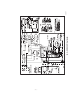
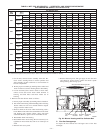
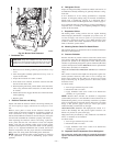
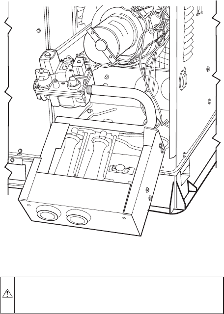
Fig. 28—Burner Rack Removed
C99086
—23—