


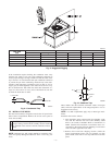
3. Secure flue hood to flue panel by inserting a single screw on
the right side and the left side of the hood.
VIII. INSTALL GAS PIPING
The gas supply pipe enters the unit through the access hole
provided. The gas connection to the unit is made to the 1/2-in. FPT
gas inlet on the manual shutoff or gas valve.
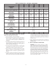
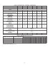
Install a gas supply line that runs to the heating section. Refer to
Table 4 and the NFGC for gas pipe sizing. Do not use cast-iron
pipe. It is recommended that a black iron pipe is used. check the
local utility for recommendations concerning existing lines. Size
gas supply piping for 0.5 in. wg maximum pressure drop. Never
use pipe smaller than the 1/2-in. FPT gas inlet on the unit gas
valve.
For natural gas applications, the gas pressure at unit gas connection
must not be less than 4.0 in. wg or greater than 13 in. wg while the
unit is operating. For propane applications, the gas pressure must
not be less than 7.0 in. wg or greater than 13 in. wg at the unit
connection.
A 1/8-in. NPT plugged tapping accessible for test gauge connec-
tion must be installed immediately upstream of the gas supply
connection to the gas valve.
When installing the gas supply line, observe local codes pertaining
to gas pipe installations. Refer to the NFGC ANSI Z223.1, NFPA
54 latest edition (in Canada, CAN/CGA B149.1, B149.2 latest
edition). In the absence of local building codes, adhere to the
following pertinent recommendations:
1. Avoid low spots in long runs of pipe. Grade all pipe 1/4 in.
in every 15 ft. to prevent traps. Grade all horizontal runs
downward to risers. Use risers to connect to heating section
and to meter.
2. Protect all segments of piping system against physical and
thermal damage. Support all piping with appropriate straps,
hangers, etc. Use a minimum of one hanger every 6 ft. For
pipe sizes larger than 1/2 in., follow recommendations of
national codes.
3. Apply joint compound (pipe dope) sparingly and only to
male threads of joint when making pipe connections. Use
only pipe dope that is resistant to action of liquefied
petroleum gases as specified by local and/or national codes.
Never use Teflon tape.
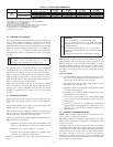
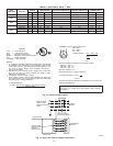
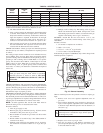
4. Install sediment trap in riser leading to heating section per
Fig. 10. This drip leg functions as a trap for dirt and
condensate.
5. Install an accessible, external, manual main shutoff valve in
gas supply pipe within 6 ft. of heating section.
6. Install ground-joint union close to heating section between
unit manual shutoff and external manual main shutoff
valve.
7. Pressure-test all gas piping in accordance with local and
national plumbing and gas codes before connection of
piping to unit.
NOTE: The supply piping must be disconnected from the gas
valve during the testing of the piping systems when test pressure is
in excess of 0.5 psig (13.8 WC). If the test pressure is equal to or
less than 0.5 psig, the unit heating section must be isolated from
the gas piping system by closing the external main manual shutoff
valve and slightly opening the ground-joint union.
CAUTION: Unstable operation may occur when the gas
valve and manifold assembly are forced out of position
while connecting improperly routed rigid gas piping to
the gas valve. Use a backup wrench when making
connection to avoid strain on, or distortion of, the gas
control piping.
CAUTION: If a flexible conductor is required or al-
lowed by the authority having jurisdiction, black iron
pipe shall be installed at the gas valve and shall extend a
minimum of 2 in. outside the unit casing.
WARNING: Never use a match or other open flame
when checking for gas leaks. Never purge gas line into
combustion chamber. Failure to follow this warning
could result in an explosion causing serious injury or
death
8. Check for gas leaks at the field-installed and factory-
installed gas lines after all piping connections have been
completed. Use soap and water solution (or method speci-
fied by local codes and/or regulations).
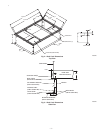
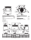
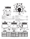
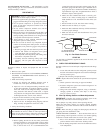
IX. INSTALL DUCT CONNECTIONS
The unit has duct flanges on the supply- and return-air openings on
the side and bottom of the unit. For downshot applications the
ductwork can be connected to the roof curb. See Fig. 6 and 7 for
connection sizes and locations.
CONFIGURING UNITS FOR DOWNFLOW (VERTICAL) DIS-
CHARGE
WARNING: Before performing service or maintenance
operations on the system, turn off main power to unit.
Electrical shock could cause serious injury or death.
1. Open all electrical disconnects before starting any service
work.
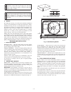
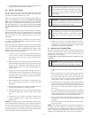
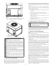
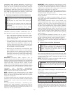
2. Remove return duct cover located on duct panel by breaking
connecting tabs with screwdriver and a hammer (Fig. 11).
3. To remove supply duct cover, break front and right side
connecting tabs with a screwdriver and a hammer. Push
louver down to break rear and left side tabs (Fig. 12).
4. If unit ductwork is to be attached to vertical opening flanges
on the unit basepan (jackstand applications only), do so at
this time. Collect ALL screws that were removed. Do not
leave screws on rooftop as permanent damage to the roof
may occur.
5. It is recommended that the basepan insulation around the
perimeter of the vertical return-air opening be secured to the
basepan with aluminum tape. Applicable local codes may
require aluminum tape to prevent exposed fiberglass.
6. Cover both horizontal duct openings with the duct covers
from the accessory duct cover kit. Ensure opening is air-and
watertight.
7. After completing unit conversion, perform all safety checks
and power up unit.
NOTE: The design and installation of the duct system must be in
accordance with the standards of the NFPA for installation of
nonresidence-type air conditioning and ventilating systems, NFPA
90A or residence-type, NFPA 90B; and/or local codes and
residence-type, NFPA 90B; and/or local codes and ordinances.
—8—