


TRANSFORMER PROTECTION — The transformer is of the
energy-limiting type. It is set to withstand a 30-second overload or
shorted secondary condition.
PRE-START-UP
WARNING: Failure to observe the following warnings
could result in serious injury or death:
1. Follow recognized safety practices and wear protective
goggles when checking or servicing refrigerant system.
2. Do not operate compressor or provide any electric
power to unit unless compressor terminal cover is in
place and secured.
3. Do not remove compressor terminal cover until all
electrical sources are disconnected.
4. Relieve and recover all refrigerant from both high- and
low-pressure sides of system before touching or dis-
turbing anything inside terminal box if refrigerant leak
is suspected around compressor terminals.
5. Never attempt to repair soldered connection while
refrigerant system is under pressure.
6. Do not use torch to remove any component. System
contains oil and refrigerant under pressure. To remove
a component, wear protective goggles and proceed as
follows:
a. Shut off gas supply and then electrical power to unit.
b. Relieve and reclaim all refrigerant from system
using both high- and low-pressure ports.
c. Cut component connecting tubing with tubing cutter
and remove component from unit.
d. Carefully unsweat remaining tubing stubs when
necessary. Oil can ignite when exposed to torch
flame.
Proceed as follows to inspect and prepare the unit for initial
startup:
1. Remove access panel.
2. Read and follow instructions on all DANGER, WARNING,
CAUTION, and INFORMATION labels attached to, or
shipped with, unit.
3. Make the following inspections:
a. Inspect for shipping and handling damages such as
broken lines, loose parts, disconnected wires, etc.
b. Inspect for oil at all refrigerant tubing connections and
on unit base. Detecting oil generally indicates a refrig-
erant leak. Leak test all refrigerant tubing connections
using electronic leak detector, halide torch, or liquid-
soap solution. If a refrigerant leak is detected, see Check
for Refrigerant Leaks section of this manual.
c. Inspect all field- and factory-wiring connections. Be sure
that connections are completed and tight.
d. Inspect coil fins. If damaged during shipping and han-
dling, carefully straighten fins with a fin comb.
4. Verify the following conditions:
WARNING: Do not purge gas supply into the combus-
tion chamber. Do not use a match or other open flame to
check for gas leaks. Failure to follow this warning could
result in an explosion causing serious injury or death.
a. Before lighting the unit for the first time, perform the
following with the gas valve in the "OFF" position: If the
gas supply pipe was not purged before connecting the
unit, it will be full of air. It is recommended that the
ground joint union be loosened, and the supply line be
allowed to purge until the odor of gas is detected. Never
purge gas lines into a combustion chamber. Immediately
upon detection of gas odor, re-tighten the union. Allow 5
minutes to elapse, then light unit.
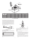
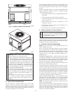
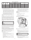
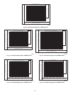
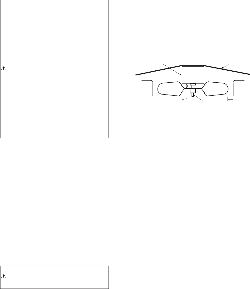
b. Make sure that condenser-fan blade is correctly posi-
tioned in fan orifice. Leading edge of condenser-fan
blade should be 1/2 in. maximum from fan orifice (see
Fig. 15).
c. Ensure fan hub is 1/8 in. max from motor housing.
d. Make sure that air filter(s) is in place.
e. Make sure that condensate drain trap is filled with water
to ensure proper drainage.
f. Make sure that all tools and miscellaneous loose parts
have been removed.
START-UP
Use the Start-Up Checklist supplied at the end of this book, and
proceed as follows:
A. CHECK FOR REFRIGERANT LEAKS
Proceed as follows to locate and repair refrigerant leaks and charge
the unit:
1. Locate leak and make sure that refrigerant system pressure
has been relieved and refrigerant recovered from both high-
and low-pressure ports.
2. Repair leak following accepted practices.
NOTE: Replace filter drier whenever the system has been opened
for repair.
3. Check system for leaks using an approved method.
4. Evacuate refrigerant system and reclaim refrigerant if no
additional leaks are found.
5. Charge unit with R-410a refrigerant, using a volumetric-
charging cylinder or accurate scale. Refer to unit rating
plate for required charge.
B. Start Up Heating Section and Make Adjustments
IMPORTANT: Complete the required procedures given in the
Pre-Start-Up section above before starting the unit.
Do not jumper any safety devices when operating the unit.
Make sure that burner orifices are properly aligned. Unstable
operation may occur when the burner orifices in the manifold are
misaligned.
NOTE: Make sure that gas supply has been purged, and that all
gas piping has been checked for leaks.
CHECK HEATING CONTROL — Start and check the unit for
proper heating control operation as follows. (see furnace lighting
instructions located inside burner or blower access panel.):
1. Place room thermostat SYSTEM switch in the HEAT
position and the FAN switch in the AUTO position.
2. Set the heating temperature control of the thermostat above
room temperature.
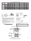
Fig. 15—Fan Blade Clearance
C99009
FAN GRILLE
MOTOR
1/8" MAX BETWEEN
MOTORAND FAN HUB
MOTOR SHAFT
1/2˝
—13—