


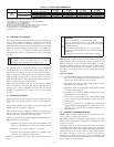
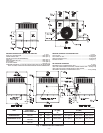
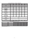
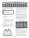
If the installation requires draining the condensate water away
from the unit, install a 2-in. trap at the condensate connection to
ensure proper drainage. See Fig. 9. Make sure that the outlet of the
trap is at least 1 in. lower than the drain pan condensate connection
to prevent the pan from overflowing. Prime the trap with water.
Connect a drain tube using a minimum of 3/4 -in. PVC or 3/4 -in.
copper pipe (all field-supplied) at the outlet end of the 2-in. trap.
Do not undersize the tube. Pitch the drain tube downward at a
slope of at least one in. for every 10 ft of horizontal run. Be sure
to check the drain tube for leaks.
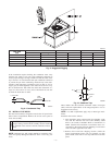
VII. INSTALL FLUE HOOD
The flue hood assembly is shipped screwed to the coil panel in the
indoor blower compartment. Remove the service access panel to
locate the assembly.
CAUTION: The venting system is designed to ensure
proper venting. The flue hood assembly must be installed
as indicated in this section of the unit installation instruc-
tions.
NOTE: Dedicated low NO
x
models MUST be installed in Cali-
fornia Air Quality Management Districts where a Low NO
x
rule
exists.
These models meet the California maximum oxides of nitrogen
(NO
x
) emissions requirements of 40 nanograms/joule or less as
shipped from the factory.
NOTE: Low NO
x
requirements apply only to natural gas instal-
lations.
Install the flue hood as follows:
1. This installation must conform with local building codes
and with the National Fuel Gas Code (NFGC), ANSI
Z223.1 (in Canada, CAN/CGA B149.1, and B149.2) or
NFPA (National Fire Protection Association) latest revi-
sion. Refer to Provincial and local plumbing or waste water
codes and other applicable local codes.
2. Remove flue hood from shipping location (inside the
blower compartment). Place vent cap assembly over flue
panel. Orient screw holes in vent cap with holes in the flue
panel.
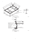
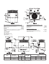
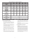
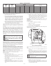
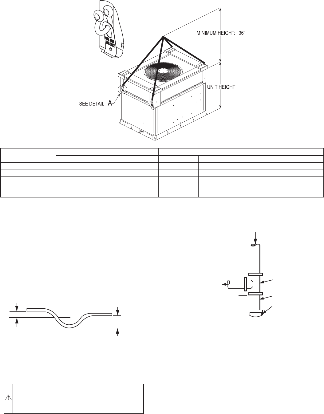
Fig. 8—Suggested Rigging
A05179
UNIT 583B
SIZE
MAXIMUM WEIGHT A B
lb kg in. mm in. mm
030 335 152 22.0 558.5 15.3 388.6
036 343 156 22.0 558.5 15.3 388.6
042 404 183 23.0 584.2 16.3 414.0
048 443 201 21.5 546.1 16.3 414.0
060 490 222 23.5 596.9 16.3 414.3
DETAIL A
Fig. 9—Condensate Trap
C99013
1” (25mm) MIN.
2” (50mm) MIN.
TRAP
OUTLET
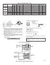
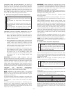
Fig. 10—Sediment Trap
C99020
OUT
TEE
NIPPLE
CAP
IN
3˝ MIN
—7—