


CAUTION: Failure to follow these precautions could
result in damage to the unit being installed:
1. Make all electrical connections in accordance with
NEC ANSI/NFPA 70 (latest edition) and local electri-
cal codes governing such wiring. In Canada, all elec-
trical connections must be in accordance with CSA
standard C22.1 Canadian Electrical Code Part 1 and
applicable local codes. Refer to unit wiring diagram.
2. Use only copper conductor for connections between
field-supplied electrical disconnect switch and unit. DO
NOT USE ALUMINUM WIRE.
3. Be sure that high-voltage power to unit is within
operating voltage range indicated on unit rating plate.
4. Do not damage internal components when drilling
through any panel to mount electrical hardware, con-
duit, etc.
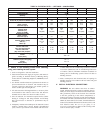
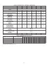
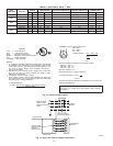
5. On 3-phase units, ensure phases are balanced within
2%. Consult local power company for correction of
improper voltage and/or phase imbalance (refer to
Table 5).
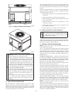
A. HIGH-VOLTAGE CONNECTIONS
The unit must have a separate electrical service with a field-
supplied, water-proof, disconnect switch mounted at, or within
sight from the unit. Refer to the unit rating plate for maximum
fuse/ circuit breaker size and minimum circuit amps (ampacity) for
wire sizing. See Table 5 for electrical data.
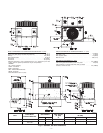
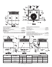
The field-supplied disconnect switch box may be mounted on the
unit over the high-voltage inlet hole when the standard power and
low-voltage entry points are used. See Fig. 6 and 7 for acceptable
location.
See unit wiring label and Fig. 14 for reference when making high
voltage connections. Proceed as follows to complete the high-
voltage connections to the unit.
1. Run the high-voltage (L1, L2, L3) and ground leads into the
control box.
2. Connect ground lead to chassis ground connection.
3. Locate the black and yellow wires connected to the lines
side of the contactor.
4. Connect field L1 to black wire on connection 11 of the
compressor contactor.
5. Connect field wire L2 to yellow wire on connection 13 of
the compressor contactor.
6. Connect field wire L3 to Blue wire from compressor.
B. Special Procedures For 208-V Operation
WARNING: Make sure that the gas supply then the
power supply to the unit is switched OFF before making
any wiring changes. Electrical shock or explosion could
cause serious injury or death.
With disconnect switch open, move yellow wire from transformer
(3/16 in.) terminal marked 230 to terminal marked 200. This retaps
transformer to primary voltage of 208 vac.
C. CONTROL VOLTAGE CONNECTIONS
NOTE: Do not use any type of power-stealing thermostat. Unit
control problems may result.
Use no. 18 American Wire Gage (AWG) color-coded, insulated
(35° C minimum) wires to make the control voltage connections
between the thermostat and the unit. If the thermostat is located
more than 100 ft from the unit (as measured along the control
voltage wires), use no. 16 AWG color-coded, insulated (35° C
minimum) wires.
STANDARD CONNECTION — Remove knockout hole located
in the flue panel adjacent to the control access panel. See Fig. 6
and 7. Remove the rubber grommet from the installer’s packet
(included with unit) and install grommet in the knockout opening.
Provide a drip loop before running wire through panel.
Run the low-voltage leads from the thermostat, through the inlet
hole, and into unit low-voltage splice box.
Locate five 18-gauge wires leaving control box. These low-voltage
connection leads can be identified by the colors red, green, yellow,
brown, and white. (See Fig. 14.) Ensure the leads are long enough
to be routed into the low-voltage splice box (located below right
side of control box). Stripped yellow wire is located in connection
box. Route leads through hole in bottom of control box and make
low-voltage connections as shown in Fig. 14. Secure all cut wires,
so that they do not interfere with operation of unit.
HEAT ANTICIPATOR SETTING — The room thermostat heat
anticipator must be properly adjusted to ensure proper heating
performance. Set the heat anticipator, using an ammeter between
the W and R terminals to determine the exact required setting.
NOTE: For thermostat selection purposes, use 0.18 amp for the
approximate required setting.
Failure to make a proper heat anticipator adjustment will result in
improper operation, discomfort to the occupants of the conditioned
space, and inefficient energy utilization; however, the required
setting may be changed slightly to provide a greater degree of
comfort for a particular installation.
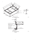
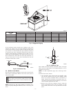
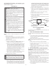
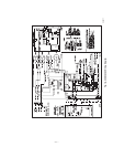
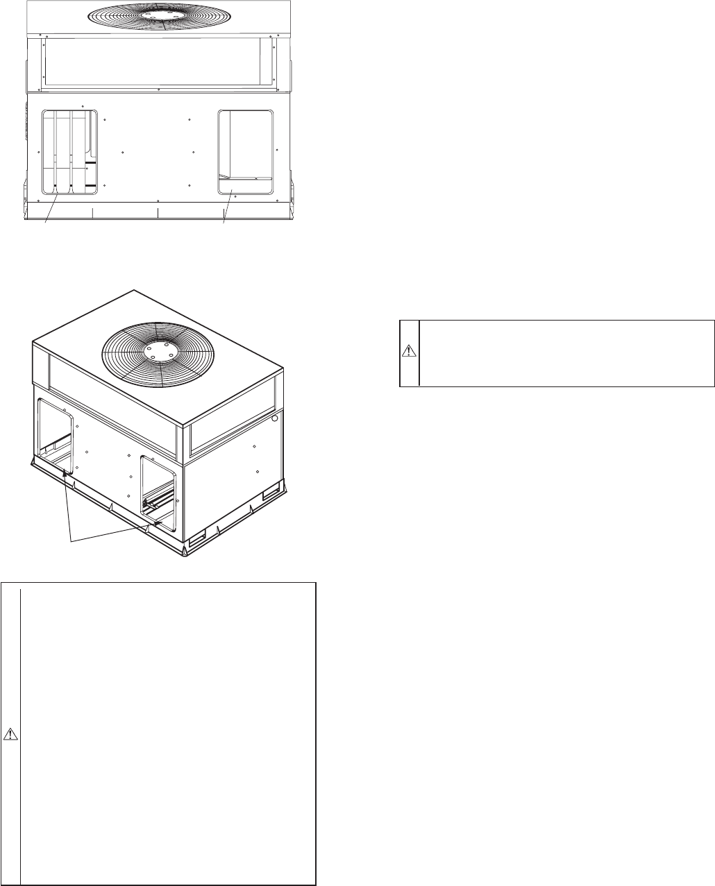
Fig. 11—Supply and Return Duct Opening
C99089
SUPPLY
DUCT
OPENING
RETURN
DUCT
OPENING
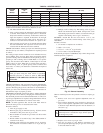
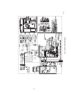
Fig. 12—Vertical Duct Cover Removed
C99012
DUCT COVERS REMOVED
—11—