


79
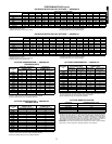
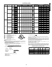
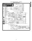
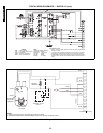
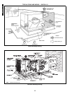
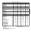
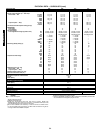
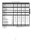
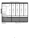
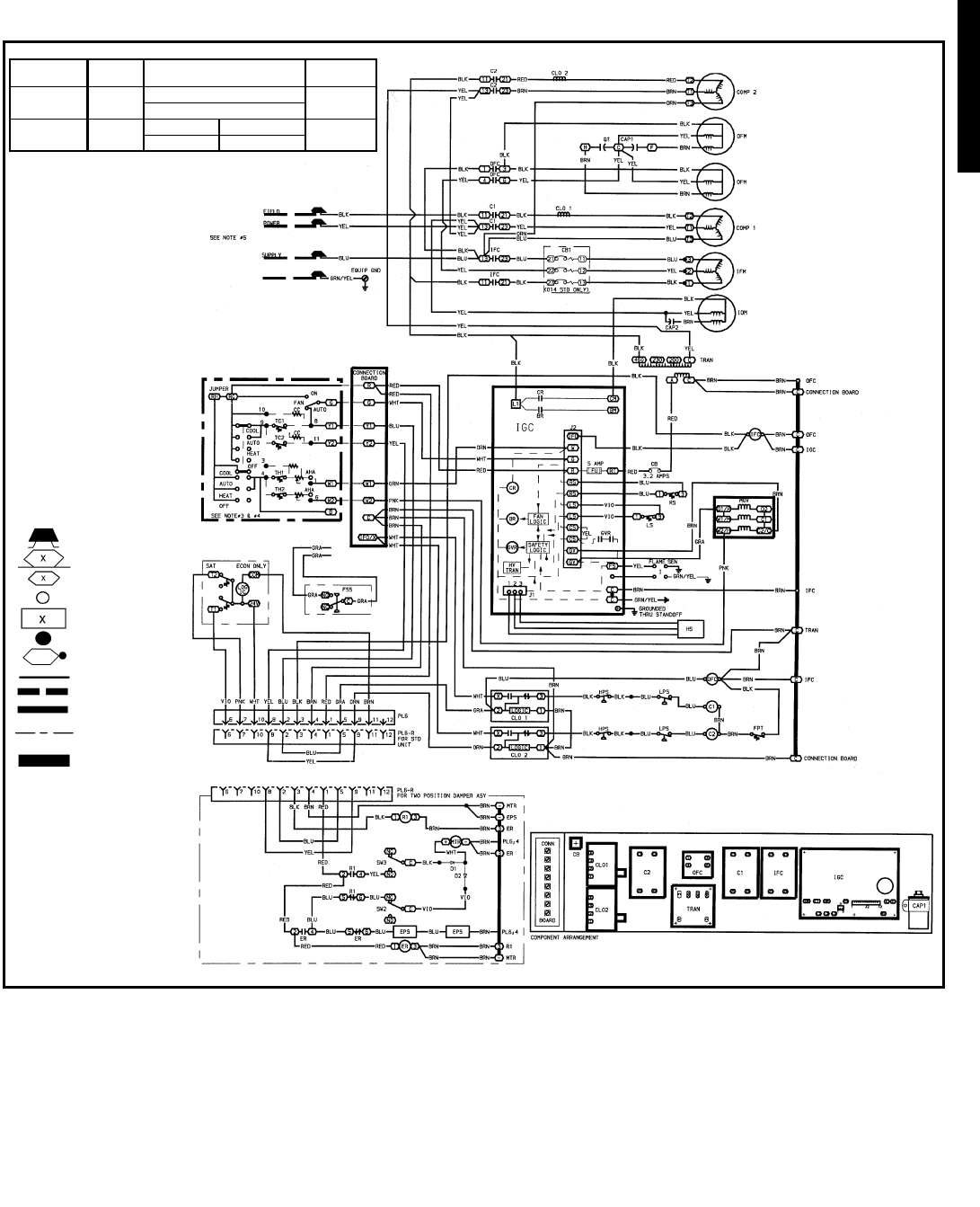
TYPICAL WIRING SCHEMATICS — 580F036-151
(580F090, 460-3-60 Shown)
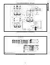
CIRCUIT
BREAKER
VOLTS MFG. PT. NO.
MUST TRIP
AMPS
CB 24 V
POTTER & BRUMFIELD
3.2
W2BX-1024-3.2
CB1
(150,151 Std)
460-3-60
Heinemann Airpax
8.5
CF3-Z228-41 219-3-2600-486
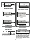
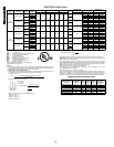
LEGEND
C—Contactor, Compressor
CAP — Capacitor
CB — Circuit Breaker
CLO — Compressor Lockout
COMP — Compressor Motor
EQUIP — Equipment
FPT — Freeze Protection Thermostat
GND — Ground
HPS — High-Pressure Switch
HS — Hall Effect Sensor
I—Ignitor
IDM — Induced Draft Motor
IFC — Indoor Fan Contactor
IFM — Indoor (Evaporator) Fan Motor
IFMOVL — Indoor Fan Motor Overload Switch
IGC — Integrated Gas Unit Controller
LPS — Low-Pressure Switch
LS — Limit Switch
MGV — Main Gas Valve
OFC — Outdoor Fan Contactor
OFM — Outdoor Fan Motor
P—Plug
PL — Plug Assembly
QT — Quadruple Terminal
RAT — Return Air Temperature
Sensor
RS — Rollout Switch
SAT — Mixed-Air Temperature
Sensor
SEN — Sensor
TRAN — Transformer
Field Splice
Marked Wire
Terminal (Marked)
Terminal (Unmarked)
Terminal Block
Splice
Splice (Marked)
Factory Wiring
Field Control Wiring
Field Power Wiring
Accessory or
Optional Wiring
To indicate common potential
only. Not to represent wiring.
a48-6270
580F036-151