


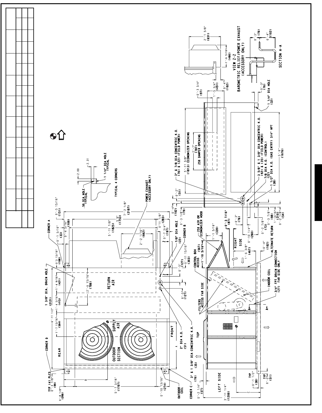
147
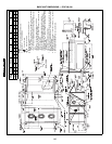
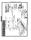
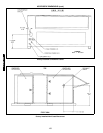
BASE UNIT DIMENSIONS — 579F240,300
NOTES:
1. Refer to print for roof curb accessory dimensions.
2. Dimensions in ( ) are in millimeters.
3. Center of Gravity.
4. Direction of airflow.
5. Ductwork to be attached to accessory roof curb only.
6. Minimum clearance:
• Rear: 7′ -0″ (2134) for coil removal. This dimension can be reduced to
4′ -0″ (1219) if conditions permit coil removal from the top.
•4′ -0″ (1219) to combustible surfaces, all four sides (includes between
units).
• Left side: 4′ -0″ (1219) for proper condenser coil airflow.
•Front: 4′ -0″ (1219) for control box access.
• Right side: 4′ -0″ (1219) for proper operation of damper and power
exhaust if so equipped.
• Top: 6′ -0″ (1829) to assure proper condenser fan operation.
• Bottom: 14″ (356) to combustible surfaces (when not using curb).
• Control box side: 3′ -0″ (914) to ungrounded surfaces, non-combusti-
ble.
• Control box side: 3′ -6″ (1067) to block or concrete walls, or other
grounded surfaces.
• Local codes or jurisdiction may prevail.
7. With the exception of clearance for the condenser coil and the damper/
power exhaust as stated in Note #6, a removable fence or barricade
requires no clearance.
8. Dimensions are from outside of corner post. Allow 0′ -
5
/
16
″ (8) on each
side for top cover drip edge.
9. See drawing 50TJ500353 for service option details.
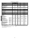
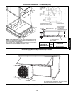
UNIT
579F
STD UNIT
WEIGHT
ECONOMIZER
WEIGHT
CORNER
A
CORNER
B
CORNER
C
CORNER
D
DIM A DIM B DIM C
Lb Kg Lb Kg Lb Kg Lb Kg Lb Kg Lb Kg ft-in. mm ft-in. mm ft-in. mm
240 1850 839 90 41 443 201 406 184 476 216 525 238 3-2 965 3-5 1041 1-8 508
300 2000 907 90 41 471 214 428 194 526 239 574 260 3-2 965 3-5 1041 1-8 508
a48-7339
0TFQ004-012
579F180-300