144
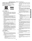
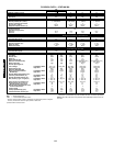
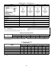
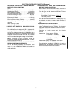
PHYSICAL DATA — 579F180-300
LEGEND
*Circuit 1 uses the lower portion of condenser coil and lower portion of evapora-
tor coils; and Circuit 2 uses the upper portion of both coils.
†Rollout switch is manual reset.
**The 579F300 units requires 2-in. industrial-grade filters capable of handling face
velocities of up to 625 ft/min (such as American Air Filter no. 5700 or equivalent).
NOTE: The 579F units have a low-pressure switch (standard) located on the suc-
tion side.
UNIT 579F
180
216 240 300
208/230, 460 v 575 v
NOMINAL CAPACITY (tons) 15 18 20 25
OPERATING WEIGHT (lb) 1650 1800 1850 2000
Economizer 90 90 90 90
Roof Curb 200 200 200 200
COMPRESSOR Scroll
Quantity...Model (Ckt 1, Ckt 2)
2...SR*942AE
2
90, 90
1...SM120,
1...SR*782AE
1...SM120,
1...SM110
1...SM161,
1...SM120
Number of Refrigerant Circuits 22 2
Oil (oz) (Ckt 1, Ckt 2) 110, 72 110,110 112, 110
Stages of Capacity Control (%) 50/50 60/40 52/48 56/44
REFRIGERANT TYPE R-22
Expansion Device TXV
Operating Charge (lb-oz)
Circuit 1* 10-13
10-5
15-2 16-3 21-0
Circuit 2 11-5 14-8 15-4
CONDENSER COIL Cross-Hatched
3
/
8
-in. Copper Tubes, Aluminum Lanced,
Aluminum Pre-Coated, or Copper Plate Fins
Rows...Fins/in. 2...17
21.7
3...15 3...15 4...15
Total Face Area (sq ft) 21.7 21.7 21.7
CONDENSER FAN Propeller Type
Nominal Cfm 10,400 9300 13,700 12,500
Quantity...Diameter (in.) 3...22 3...22 2...30 2...30
Motor Hp...Rpm
1
/
2
...1050
1
/
2
...1050 1...1075 1...1075
Watts Input (Total) 1100 1100 3400 3400
EVAPORATOR COIL Cross-Hatched
3
/
8
-in. Copper Tubes, Aluminum Lanced or
Copper Plate Fins, Face Split
Rows...Fins/in. 2...17 3...15 3...15 4...15
Total Face Area (sq ft) 17.5 17.5 17.5 17.5
EVAPORATOR FAN Centrifugal Type
Quantity...Size (in.) 2...10 x 10 2...10 x 10 2...12 x 12 2...12 x 12 2...12 x 12
Type Drive Belt Belt Belt Belt Belt
Nominal Cfm 6000 6000 7200 8000 10,000
Motor Hp 3.7 3.0 5 7.5 10
Motor Nominal Rpm 1725 1725 1745 1745 1740
Maximum Continuous Bhp 4.25 3.45 5.90
8.7 [208/230, 575 v]
9.5 [460 v]
10.2 [208/230, 575 v]
11.8 [460 v]
Motor Frame Size 56H 56H 184T 213T 215T
Nominal Rpm High/Low ——— — —
Fan r/s Range Low-Medium Static 891-1179 1159-1429 910-1095 1002-1225 1066-1283
High Static 1227-1550 — 1069-1287 1193-1458 1332-1550
Motor Bearing Type Ball Ball Ball Ball Ball
Maximum Allowable Rpm 1550 1550 1550 1550 1550
Motor Pulley Pitch Diameter Low-Medium Static 3.1/4.1 4.3/5.3 4.9/5.9 5.4/6.6 4.9/5.9
Min/Max (in.) High Static 3.7/4.7 — 4.9/5.9 5.4/6.6 4.9/5.9
Nominal Motor Shaft Diameter (in.)
7
/
8
7
/
8
1
1
/
8
1
3
/
8
1
3
/
8
Fan Pulley Pitch Diameter (in.) Low-Medium Static 6.0 6.4 9.4 9.4 8.0
High Static 5.2 — 8.0 7.9 6.4
Nominal Fan Shaft Diameter (in.) 1
3
/
16
1
3
/
16
1
7
/
16
1
7
/
16
1
7
/
16
Belt, Quantity...Type...Length (in.) Low-Medium Static 1...BX...42 1...BX...45 1...BX...50 1...BX...54 2...BX...50
High Static 1...BX...42 — 1...BX...48 1...BX...50 2...BX...47
Pulley Center Line Distance (in.) 13.5-15.5 13.5-15.5 13.3-14.8 14.6-15.4 14.6-15.4
Speed Change per Full Turn of
Movable Pulley Flange (rpm)
Low-Medium Static 48 44 37 37 36
High Static 55 — 34 44 45
Movable Pulley Maximum Full Turns
From Closed Position 555 5 5
Factory Speed 3.5 3.5 3.5 3.5 3.5
Factory Speed Setting (rpm) Low-Medium Static 1035 1296 1002 1120 1182
High Static 1389 — 1178 1328 1470
Fan Shaft Diameter at Pulley (in.) 1
3
/
16
1
3
/
16
1
7
/
16
1
7
/
16
1
7
/
16
Bhp — Brake Horsepower
TXV — Thermostatic Expansion Valve
0TFQ004-012
579F180-300


