


201
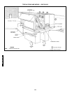
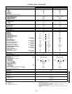
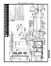
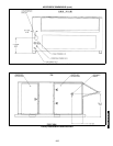
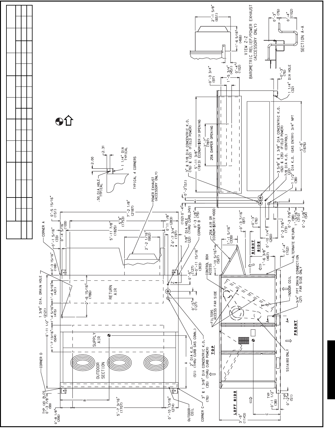
BASE UNIT DIMENSIONS — 581A155,180
UNIT
581A
STD UNIT
WEIGHT
ECONOMI$ER IV
WEIGHT
CORNER
A
CORNER
B
CORNER
C
CORNER
D
DIM A DIM B DIM C
Lb Kg Lb Kg Lb Kg Lb Kg Lb Kg Lb Kg ft-in. mm ft-in. mm ft-in. mm
155 1725 782 90 41 407 185 375 170 383 174 410 186 3-3 991 3- 5 1051 1-10 559
180 1800 816 90 41 417 189 399 181 481 218 503 228 3- 2 961 3-6 1070 1-10 559
NOTES:
1. Refer to print for roof curb accessory dimensions.
2. Dimensions in ( ) are in millimeters.
3. Center of Gravity.
4. Direction of airflow.
5. Ductwork to be attached to accessory roof curb only.
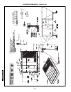
6. Minimum clearance:
• Rear: 7′ -0″ (2134) for coil removal. This dimension can be reduced to
4′ -0″ (1219) if conditions permit coil removal from the top.
•4′ -0″ (1219) to combustible surfaces, all four sides (includes between
units).
• Left side: 4′ -0″ (1219) for proper condenser coil airflow.
• Front: 4′ -0″ (1219) for control box access.
• Right side: 4′ -0″ (1219) for proper operation of damper and power
exhaust if so equipped.
•Top: 6′ -0″ (1829) to assure proper condenser fan operation.
• Bottom: 14″ (356) to combustible surfaces (when not using curb).
• Control box side: 3′ -0″ (914) to ungrounded surfaces, non-combustible.
• Control box side: 3′ -6″ (1067) to block or concrete walls, or other
grounded surfaces.
• Local codes or jurisdiction may prevail.
7. With the exception of clearance for the condenser coil and the damper/
power exhaust as stated in Note #6, a removable fence or barricade
requires no clearance.
8. Dimensions are from outside of corner post. Allow 0′ -
5
/
16
″ (8) on each
side for top cover drip edge.
a48-8219
581A155-300