


261
CONTROLS (cont)
When the thermostat is satisfied and W1 and W2 are deener-
gized, the IFM continues to run and the economizer damper
then moves to the minimum position.
Units With Hot Gas Bypass Dehumidification Package —
When thermostat calls for cooling, terminals G and Y1 and Y2
and the compressor contactors C1 and C2 are energized. The
indoor (evaporator) fan motor (IFM), compressor, and outdoor
(condenser) fan motor (OFM) start. The OFM runs continuously
while the unit is in cooling. As shipped from the factory, hot gas
bypass dehumidification circuit is always energized. If hot gas
bypass circuit modulation is desired, a field-installed, wall-
mounted humidistat is required.
If the hot gas bypass humidistat is installed and calls for the hot
gas bypass subcooler coil to operate, the humidistat internal
switch closes. This energizes and closes the liquid line solenoid
valve coil (LLSV) of the hot gas bypass circuit, forcing the hot
liquid refrigerant of the liquid line to enter the subcooler coil. As
the hot liquid passes through the subcooler coil, it is exposed to
the cold supply airflow coming off from the evaporator coil and
the liquid is further cooled to a temperature approaching the
evaporator coil leaving-air temperature. The state of the refrig-
erant leaving the subcooler coil is a highly subcooled liquid
refrigerant. The liquid then enters a thermostatic expansion
valve (TXV) where the liquid is dropped to a lower pressure.
The TXV does not have a pressure drop great enough to
change the liquid to a 2-phase fluid. The TXV can throttle the
pressure drop of the liquid refrigerant and maintain proper con-
ditions at the compressor suction valve over a wide range of
operating conditions. The liquid then enters a second fixed
restrictor expansion device for a second pressure drop to a
2-phase fluid. The liquid proceeds to the evaporator coil at a
temperature lower than normal cooling operation. This lower
temperature is what increases the latent capacity of the rooftop.
The 2-phase refrigerant passes through the evaporator and is
changed into a vapor. The air passing over the evaporator coil
will become colder than during normal operation as a result of
the colder refrigerant temperatures. However, as it passes over
the subcooler coil, the air will be warmed slightly.
As the refrigerant leaves the evaporator, the refrigerant passes
a low-pressure switch in the suction line. This low-pressure
switch will de-activate the hot gas bypass package when the
suction pressure reaches 60 psig. The low-pressure switch is
an added safety device to protect against evaporator coil
freeze-up. The low-pressure switch will only de-activate and
open the liquid line solenoid valve in the hot gas bypass circuit.
The compressors will continue to run as long as there is a call
for cooling, regardless of the position of the low-pressure
switch. The solenoid valve and the hot gas bypass package will
be re-activated only when the call for cooling has been satisfied,
the low-pressure switch has closed, and a new call for cooling
exists. The crankcase heaters on the scroll compressor provide
additional protection for the compressor due to the additional
refrigerant charge in the subcooler.
When the humidistat is satisfied, the humidistat internal switch
opens cutting power to and opening the LLSV. The refrigerant is
routed back through the evaporator and the subcooler coil is
removed from the refrigerant loop.
When the thermostat is satisfied, C1 and C2 are deenergized
and the compressor and OFM shut off. After a 30-second delay,
the IFM shuts off. If the thermostat fan selector switch is in the
ON position, the IFM will run continuously.
OPERATING SEQUENCE, 581A210-300
Cooling, Units Without Economizer — When thermostat calls
for cooling, terminals G and Y1 are energized. The indoor-fan
contactor (IFC) and compressor contactors A1 and B1 (except
300 units) are energized and indoor-fan motor, compressor, and
outdoor fan starts. The outdoor fan motor runs continuously
while unit is cooling. If further cooling is required, the Y2 output
from the thermostat energizes compressor contactor C1 (B1 on
300 units).
Heating, Units Without Economizer
NOTE: The 581A210-300 units have 2 stages of heat.
When the thermostat calls for heating, power is sent to W on the
IGC (integrated gas unit controller) board. An LED (light-
emitting diode) on the IGC board will be on during normal oper-
ation. A check is made to ensure that the rollout switch and limit
switch are closed and the induced-draft motor is running.
The induced-draft motor is then energized, and when speed is
proven with the hall effect sensor on the motor, the ignition acti-
vation period begins. The burners will ignite within 5 seconds.
If the burners do not light, there is a 22-second delay before
another 5-second attempt. If the burners still do not light, this
sequence is repeated for 15 minutes. After the 15 minutes have
elapsed, if the burners still have not lit, heating is locked out.
To reset the control, break 24-v power to the thermostat. When
ignition occurs the IGC board will continue to monitor the condi-
tion of the rollout and limit switches, the hall effect sensor, as
well as the flame sensor. If the unit is controlled through a room
thermostat set for fan auto., 45 seconds after ignition occurs,
the indoor-fan motor will be energized (and the outdoor-air
dampers will open to their minimum position). If for some rea-
son the overtemperature limit opens prior to the start of the
indoor fan blower, on the next attempt, the 45-second delay will
be shortened to 5 seconds less than the time from initiation of
heat to when the limit tripped. Gas will not be interrupted to the
burners and heating will continue.
Once modified, the fan on delay will not change back to
45 seconds unless power is reset to the control.
When additional heat is required, W2 closes and initiates power
to the second stage of the main gas valve. When the thermostat
is satisfied, W1 and W2 open and the gas valve closes, inter-
rupting the flow of gas to the main burners. If the call for W1
lasted less than 1 minute, the heating cycle will not terminate
until 1 minute after W1 became active. If the unit is controlled
through a room thermostat set for fan auto., the indoor-fan
motor will continue to operate for an additional 45 seconds then
stop (and the outdoor-air dampers will close).
If the overtemperature limit opens after the indoor motor is
stopped within 10 minutes of W1 becoming inactive, on the next
cycle the time will be extended by 15 seconds. The maximum
delay is 3 minutes. Once modified, the fan off delay will not
change back to 45 seconds unless power is reset to the control.
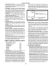
A LED indicator is provided on the IGC to monitor operation.
The IGC is located by removing the side panel and viewing the
IGC through the view port located in the control box access
panel. During normal operation, the LED is continuously on.
Cooling, Units With EconoMi$er IV — When free cooling is
not available, the compressors will be controlled by the zone
thermostat. When free cooling is available, the outdoor-air
damper is modulated by the EconoMi$er IV control to provide a
50 to 55 F mixed-air temperature into the zone. As the mixed-air
temperature fluctuates above 55 or below 50 F, the dampers will
be modulated (open or close) to bring the mixed-air tempera-
ture back within control.
If mechanical cooling is utilized with free cooling, the outdoor-air
damper will maintain its current position at the time the com-
pressor is started. If the increase in cooling capacity causes the
mixed-air temperature to drop below 45 F, then the outdoor-air
damper position will be decreased to the minimum position. If
the mixed-air temperature continues to fall, the outdoor-air
damper will close. Control returns to normal once the mixed-air
temperature rises above 48 F.
If optional power exhaust is installed, as the outdoor-air damper
opens and closes, the power exhaust fans will be energized and
deenergized.