


92
c. Disconnect Switch Bracket
(1.) Provides a pre--engineered and sized mounting bracket for applications requiring a unit mounted fused
disconnect of greater than 100 amps. Bracket assures that no damage will occur to coils when mounting
with screws and other fasteners.
11. Flue Discharge Deflector:
a. Flue discharge deflec tor shall direct unit exhaust vertically instead of horizontally.
b. Deflector shall be defined as a “natural dra ft” device by the National Fuel and Gas (NFG) code.
12. Thru--the--Base Connect ors:
a. Kits shall provide connectors to permit gas and electrical connections to be brought to the unit through the
unit basepan.
b. Minimum of four connection locations per unit.
13. Supply Duct Cover (16 size only):
a. Required when field converting the factory standard vertical duct supply to horizontal duct supply configura-
tion. One required per unit.
14. Propeller Power Exhaust:
a. Power exhaust sha ll be used in conjunction with an integrated economizer.
b. Independent modules for vertical or horizontal return configurations shall be available.
c. Horizontal power exhaust shall be mounted in return ductwork.
d. Power exhaust shall be controlled by economizer controller operation. Exhaust fans shal l be energized when
dampe rs open past the 0--100% adjustable setpoint on the economize r control.
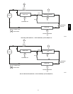
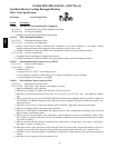
15. Roof Curbs (Vertical):
a. Full perimeter roof curb with exhaust capability providing separate air streams for energy recovery from the
exhaust air without supply air contamination.
b. Formed galvanized steel with wood nailer strip and shall be capable of supporting entire unit weight.
c. Permits installation and securing of ductwork to curb prior to mounting unit on t he curb.
16. High Altitude Gas Conversion Kit:
a. Package shall contain all the necessary hardware and instructions to convert a standard natural gas unit to op-
erate from 2000--7000 ft (610 to 2134m) elevati on with natural gas or from 0--7000 ft (90--2134m) elevation
with liquefied propane.
17. Outdoor Air Enthalpy Sensor:
a. The outdoor air enthalpy sensor shall be used to provide single enthalpy control. When used in conjunction
with a return air enthalpy sensor, the unit will provide differential enthalpy control. The sensor allows the unit
to determine if outside air is suitable for free cooling.
18. Return Air Enthalpy Sensor:
a. The return air enthalpy sensor shall be used in conjunction with an outdoor air enthalpy sensor to provide dif-
ferential enthalpy control.
19. Indoor Air Quality (CO
2
)Sensor:
a. Shall be able to provide demand ventilation indoor air quality (IAQ) control.
b. The IAQ sensor shall be availa ble in duct mount, wall mount, or wall mount with LED display. The setpoint
shall have adjustment capability.
20. Smoke detectors (factory installed only):
a. Shall be a Four--Wire Controller and Dete ctor.
b. Shall be environmental compensated with differential sensing for reliable, stable, and drift--free sensitivity.
c. Shall use magnet --activated test/reset sensor switches.
d. Shall have tool--less connection terminal access.
e. Shall have a recessed momentary switch for testing and resetting the detector.
f. Controller shall include:
(1.) One set of normally open alarm initiation contacts for connection to an initiating device circuit on a fire
alarm control panel.
(2.) Two Form--C auxiliary alarm relays for interface with rooftop unit or other equipment.
(3.) One Form--C supervision (trouble) relay to control the operation of the Troubl e LED on a rem ote test/reset
station.
(4.) Capabl e of direct connection to two individual detector modules.
(5.) Can be wired to up to 14 other duct smoke detectors for multiple fan shutdown applications
580J