


9
Crankcase Heater Operation
This unit has an internal crankcase heater that will be energized
during the off cycle and is intelligently demanded by the system to
prevent the compressor from being the coldest part of the system
thus enhancing the reliability. The crankcase heater will function
as needed any time the outdoor unit is powered. The indoor unit
and UI do not need to be installed for the crankcase heater to
operate properly.
NOTE: Contactor may close intermittently without the unit
starting. This is done to determine whether the control needs to
energize the crankcase heater. Closing the contactor powers the
inverter and allows the system to check compressor temperature.
Outdoor Fan Motor Operation
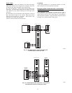
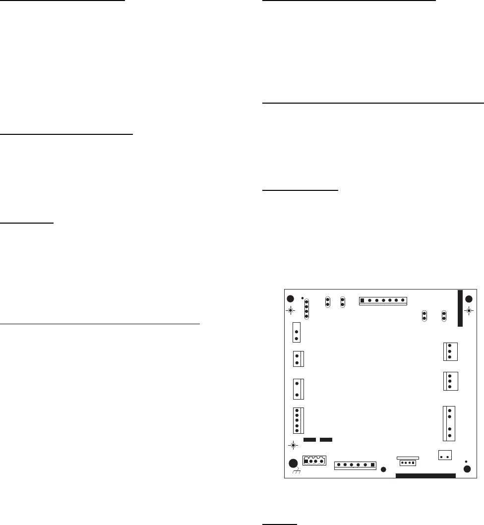
The outdoor unit control (Fig. 11) energizes outdoor fan anytime
compressor is operating, except for defrost and as needed during
low--ambient cooling operation. The outdoor fan remains
energized if a pressure switch opens or compressor scroll over
temperature should occur. This OD fan is an ECM motor which
operates at varying speeds depending on the ambient and the
demand.
Time Delays
The unit time delays include:
S Five minute time delay to start cooling or heating operation when
there is a call from the user interface. To bypass this feature,
momentarily short and releaseForced Defrost pins.
S Five minute compressor re--cycle delay on return from a
brown--out condition.
S See Table 7 for other delay information.
General Information
Evolution Controlled low ambient
cooling:
This unit is capable of low ambient cooling down to 0F (--17.8C)
with Low Ambient enabled on the Evolution Control. A low
ambient kit is not required. The only accessory that may be
required is wind baffles in locations which are likely to experience
cross winds in excess of 5 miles an hour. This generally occurs
only on roof and open area applications. The Evolution Control
provides an automatic evaporator freeze thermostat. Low ambient
cooling must be enabled in the User Interface setup. Fan may not
begin to cycle until about 40F(4.4C) OAT. Fan will cycle based
on coil and outdoor air temperature.
Evolution controlled low ambient mode operates as follows:
S Fan is OFF when outdoor coil temperature is too low (+
55_F/12.7_C), the saturated suction pressure indicates a freezing
indoor coil or outdoor fan has been ON for 30 minutes. (Fan is
turned off to allow refrigerant system to stabilize.)
S Fan is ON when outdoor coil temperature is too high
(+80_F/26.7_C), the high side pressure is too high or if outdoor
fan has been OFF for 30 minutes. (Fan is turned on to allow
refrigerant system to stabilize)
S Low pressure indication by the suction pressure transducer is
ignored for first 3 minutes during low ambient start up. After 3
minutes, if low pressure trip occurs, then outdoor fan motor is
turned off for 10 minutes, with the compressor running. If
pressure condition is satisfied within 10 minutes then cooling
continues with the outdoor fan cycling per the coil temperature
routine listed abovefor theremainder of the cooling cycle. If the
suction pressure condition is not satisfied within 10 minutes, then
the normal trip response (shut down cooling operation and
generate LP trip error) will occur.
Utility Interface With Evolution Control
The utility curtailment relay should be wired between the two
UTIL connections on the control board for this Evolution
Communicating System (see Fig. 20). This input allows a power
utility device to interrupt compressor operation during peak load
periods. When the utility sends a signal to shut the system down,
the User Interface will display, ”Curtailment Active”. See UI
installation instructions for setup details.
Communication and Status Function Lights
Evolution Control, Green Communications (COMM)Light
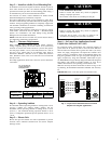
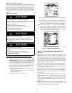
A green LED (COMM light) on the outdoor board (see Fig. 11)
indicates successful communication with the other system
products. The green LED will remain OFF until communication is
established. Once a valid command is received, the green LED will
turn ON continuously. If no communication is received within 2
minutes, the LED will be turned OFF until the next valid
communication.
Amber Status
Light
Amber colored STATUS light indicates operation and error status.
See Table 7 for definitions.
S Two minute time delay to return to standby operation from last
valid communication.
S One minute time delay of outdoor fan at termination of cooling
mode when outdoor ambient is greater than or equal to 100_F
(37.8_C).
S Fifteen second delay at termination of defrost before the auxiliary
heat is de--energized.
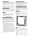
CB
MODEL
PL8
FORCED
DEFROST
J2
1
BRN
RED
SEC1
SEC2
PWM2
PWM1
INVERTER
PL1
PL2
RVS
CC
PL11
PL4
PL6
OCT
OAT
SPT
OST
A
B
C
NO
USE
UTIL
LS
Y
C
O
COMM
STATUS
YEL
BLU
EXV
PL5
PL3
HPS
A12048
Fig. 11 -- Variable Speed Control Board
Defrost
This user interface (UI) offers 5 possible defrost interval times: 30,
60, 90, 120 minutes, or AUTO. The default is AUTO.
Defrost interval times: 30, 60, 90, and 120 minutes or AUTO are
selected by the Evolution Control User Interface (dip switches are
not used.)
AUTO defrost adjusts the defrost interval time based on the last
defrost time as follows:
S When defrost time <3 minutes, the next defrost interval=120
minutes.
S When defrost time 3--5 minutes, the next defrost interval=90
minutes.
S When defrost time 5--7 minutes, the next defrost interval=60
minutes.
S When defrost time >7 minutes, the next defrost interval=30
minutes.