


6
Outdoor Unit Connected to Factory--Approved Indoor
Unit
Outdoor unit contains correct system refrigerant charge for
operation with factory--approved, AHRI--rated smallest indoor unit
when connected by 15 ft. (4.57 m) of field--supplied or
factory--accessory tubing, and factory--supplied filter drier. Check
refrigerant charge for maximum efficiency.
NOTE: If the indoor furnace coil width is more than the furnace
casing width, refer to the indoor coil Installation Instructions for
transition requirements.
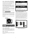
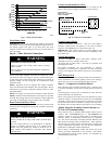
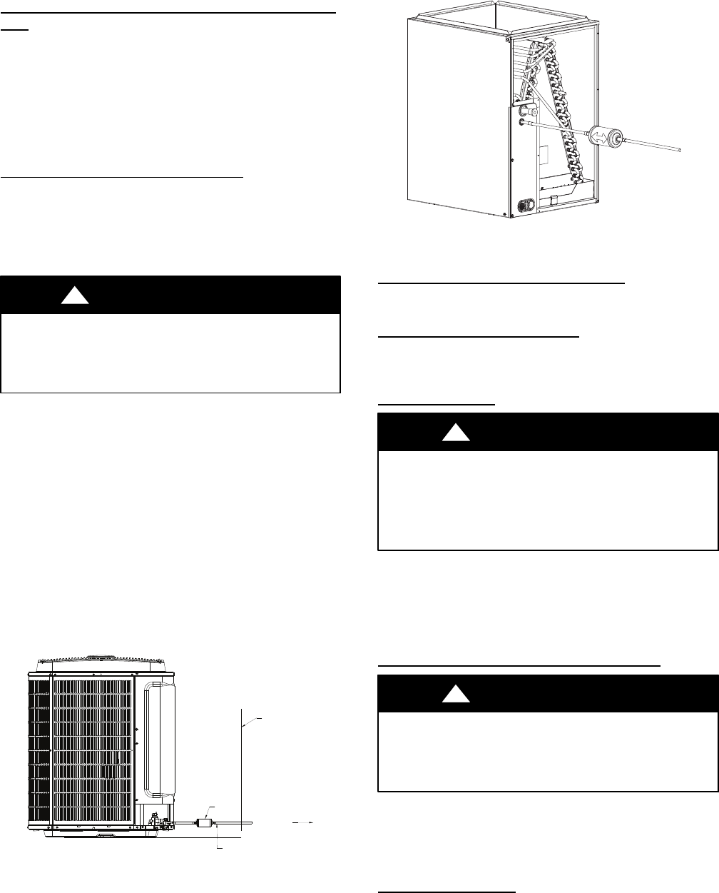
Install Liquid--Line Filter Drier Indoor
Refer to Fig. 6 and install filter drier as follows:
1. Braze 5--in. (127 mm) liquid tube to the indoor coil.
2. Wrap filter drier with damp cloth.
3. Braze filter drier to above 5--in. (127 mm) liquid tube.
4. Connect and braze liquid refrigerant tube to the filter drier.
CAUTION
!
UNIT DAMAGE HAZARD
Failure to follow this caution may result in unit damage or
improper operation.
Installation of filter drier in liquid line is required.
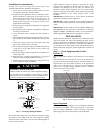
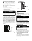
Factory Supplied Muffler (part # LM10KK003)
Installation is Required On Every Installation:
S A mufflerisrequired toreducenoise transmitted to indoorthrough
the line set.
S Mufflermustbeinstalledoutsidethedwelling. Mufflercan alsobe
installed in vertical configuration for space consideration
maintaining aminimum of 12 in (304.8 mm)straight pipesection
to the closest bend.
S Maintain at least 12 in. (304.8 mm) straight pipe length to the
muffler shell inlet and from the outlet stubs.
S To prevent rusting, provide sufficient clearance between the
mufflerandthegroundsurface.Also,position themufflersuchthat
accidental abuse (such as by a weed trimmer, lawn mower etc.) of
the painted surface is avoided. Apply touch--up paint to muffler
braze joints.
S Insulating the muffler with Armaflext tape is recommended.
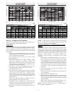
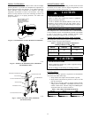
EXTERIOR
WALL
VAPOR LINE
MUFFLER
TO DWELLING
A12044
Fig. 5 -- Muffler Installation
A05227
Fig. 6 -- Liquid--Line Filter Drier
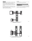
Refrigerant Tubing connection Outdoor
Connect vapor tube to fitting on outdoor unit vapor service valves
(see Table 1).
NO Installation of Adapter Tube
Although it is a heat pump this unit has a standard AC liquid
service valve. An EXV inside the unit serves as the heating
expansion device.
Sweat Connections
CAUTION
!
UNIT DAMAGE HAZARD
Failure to follow this caution may result in equipment
damage or improper operation.
S Use a brazing shield
S Wrap service valves with wet cloth or heat sink material.
Use refrigerant grade tubing. Service valves are closed from factory
and ready for brazing. After wrapping service valve with a wet
cloth, braze sweat connections using industry accepted methods
and materials. Consult local code requirements. Refrigerant tubing
and indoor coil are now ready for leak testing. This check should
include all field and factory joints.
Evacuate Refrigerant Tubing and Indoor Coil
CAUTION
!
UNIT DAMAGE HAZARD
Failure to follow this caution may result in equipment
damage or improper operation.
Never use the system compressor as a vacuum pump.
Refrigerant tubes and indoor coil should be evacuated using the
recommended deep vacuum method of 500 microns. The alternate
triple evacuation method may be used. See Service Manual for
triple evacuation method. Always break a vacuum with dry
nitrogen prior to opening the refrigerant system for servicing.
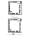
Deep Vacuum Method
The deep vacuum method requires a vacuum pump capable of
pulling a vacuum of 500 microns and a vacuum gauge capable of
accurately measuring this vacuum depth. The deep vacuum method
is the most positive way of assuring a system is free of air and
liquid water. (See Fig. 7)