


14
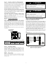
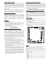
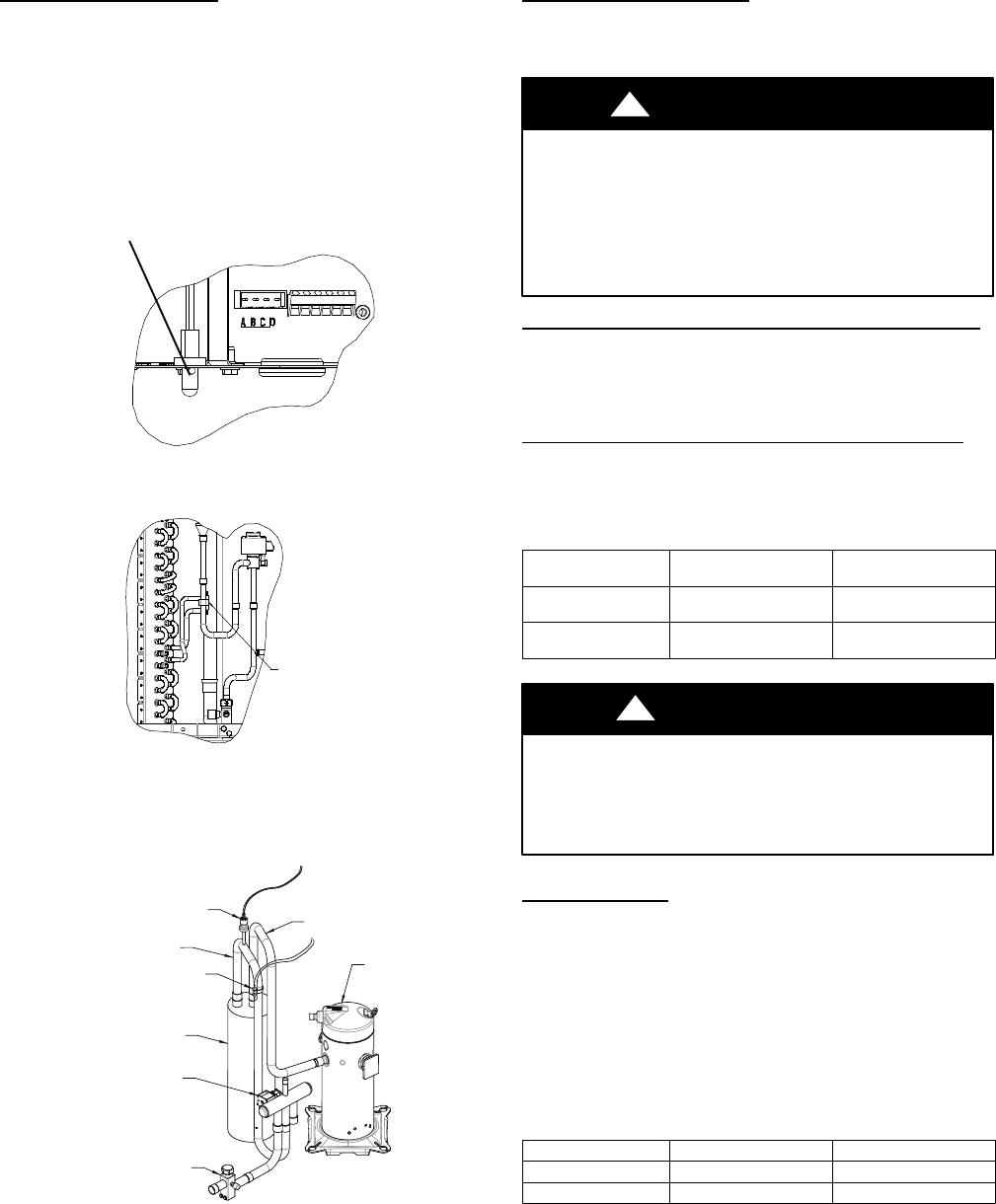
Outdoor Coil Thermistor
The outdoor coil thermistor is a 10Kohm resistor used for multiple
system operations. It provides the coil/liquid line temperature to
the heat pump board and user interface. Low ambient operation,
defrost initiation, defrost termination and assistance with OAT
temperature measurement of some of the functions. The sensor
must be securely mounted to the tube connecting the EXV and
distributor. See Fig. 15 for proper placement. See Table 4 for
proper resistances.
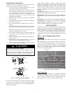
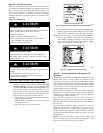
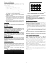
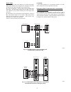
OAT Thermistor must be
locked in place with
spherical nib end facing
towards the frontof the
control box
A11142
Fig. 15 -- OAT Thermistor Location (Bottom of Control Box)
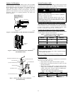
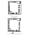
OCTSENSOR
LOCATION
A11143
Fig. 16 -- Outdoor Coil Thermistor (OCT) Attachment
(On Distributor Tube)
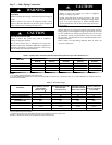
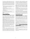
REVERSING VALVE
ACCUMULATOR
SUCTION TUBE
SUCTION THERMISTOR (OST)
SUCTION SERVICE VALVE
ACCUMULATOR TUBE
COMPRESSOR
PRESSURE TRANSDUCER (SPT)
A11103
Fig. 17 - Suction Thermistor (OST) Attachment
(On Suction Tube)
Suction Thermistor (OST)
Suction Thermistor is used for assisting in EXV control and must
be secured on the suction tube and aligned longitudinally to the
vertical surface of the tube axis (see Fig. 17).
CAUTION
!
UNIT DAMAGE HAZARD
Failure to follow this caution may result in equipment
damage or improper operation.
In order to minimize the ambient influence, make sure the
thermistor curved surface hugs the pipe surface and is
secured tight using the wire tie fished through the original
slot insulating polymer body.
Variable Speed Compressor Sensor Output Terminals
This compressor has a motor thermistor and a scroll thermistor.
Correct resistance between scroll thermistor terminal and common
is 10k at 77_F(25_C). Correct resistance between motor
thermistor terminal and common is 5k at 77_F(25_C).
Variable Speed Compressor Power Input Terminals
This compressor operates with a 3--phase variable frequency PWM
variable voltage to the three fusite terminals.
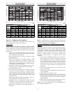
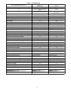
Table 5 – Variable Speed Compressor Resistances
(winding resistance at70_F 20_F)
WINDING
280ANV024
280ANV036
280ANV048
280ANV060
Between terminals
T1, T2, and T3
.681 .203
Between terminal &
ground
>1 mega OHM >1 mega OHM
UNIT DAMAGE HAZARD
Failure to follow this caution may result in equipment damage
and/or improper operation.
Do not use Meggar for measuring the winding resistance.
CAUTION
!
ECM Fan Motor
If verification of proper operation is required for the ECM motor
used in this unit, follow these steps:
1. Verify that the 230v input to the transformer is present.
2. Verify that the control board is powered 18 volts to 30 volts
from the transformer.
3. With the UI in charging mode in cooling, measure the DC
voltage between the PWM 1 and PWM 2 terminals on the
outdoor control board. The DC voltage and PWM (option-
al) measured must be as shown in Table 6.
Table 6 – DC Voltage and PWM Measurement
UnitSize Voltage PWM
024, 036 8.9 VDC 52
048, 060 11.1 VDC 84