


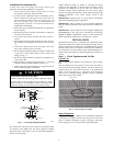
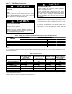
7
500
MINUTES
01234567
1000
1500
LEAK IN
SYSTEM
VACUUM TIGHT
TOO WET
TIGHT
DRY SYSTEM
2000
MICRONS
2500
3000
3500
4000
4500
5000
A95424
A95424
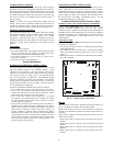
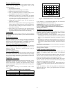
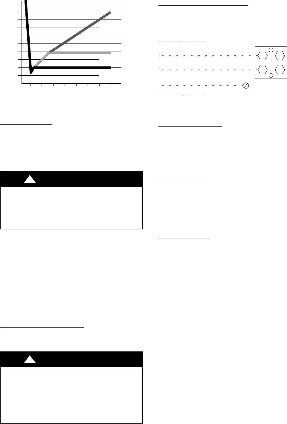
Fig. 7 -- Deep Vacuum Graph
Final Tubing Check
IMPORTANT: Check to be certain factory tubing on both indoor
and outdoor unit has not shifted during shipment. Ensure tubes are
not rubbing against each other or any sheet metal. Pay close
attention to feeder tubes, making sure wire ties on feeder tubes are
secure and tight.
Step 8 — Make Electrical Connections
!
WARNING
ELECTRICAL SHOCK HAZARD
Failure to follow this warning could result in personal
injury or death.
Do not supply power to unit with compressor terminal box
cover removed.
Be sure field wiring complies with local and national fire, safety,
and electrical codes, and voltage to system is within limits shown
on unit rating plate. Contact local power company for correction of
improper voltage. See unit rating plate for recommended circuit
protection device.
NOTE: Operation of unit on improper line voltage constitutes
abuse and could affect unit reliability. See unit rating plate. Do not
install unit in system where voltage may fluctuate above or below
permissible limits.
NOTE: Use copper wire only between disconnect switch and unit.
NOTE: Install branch circuit disconnect of adequate size per NEC
to handle unit starting current. Locate disconnect within sight from
and readily accessible from unit, per Section 440--14 of NEC.
Route Ground and Power Wires
Remove access panel to gain access to unit wiring. Extend wires
from disconnect through power wiring hole provided and into unit
control box.
!
WARNING
ELECTRICAL SHOCK HAZARD
Failure to follow this warning could result in personal injury
or death.
The unit cabinet must have an uninterrupted or unbroken
ground to minimize personal injury if an electrical fault
should occur. The ground may consist of electrical wire or
metal conduit when installed in accordance with existing
electrical codes.
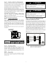
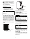
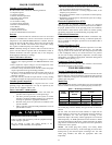
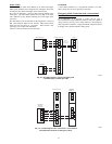
Connect Ground and Power Wires
Connect ground wire to ground connection in control box for
safety. Connect power wiring to contactor as shown in Fig. 8.
DISCONNECT
PER N. E. C.AND/OR
LOCAL CODES
CONTACTOR
GROUND
LUG
FIELD GROUND
WIRING
FIELD POWER
WIRING
A91056
Fig. 8 -- Line Power Connections
Connect Control Wiring
Connect to Evolution connections. Only two wires (AB) to
Evolution capable indoor unit (furnace or fan coil) is required.
Typical 4 wire (ABCD) may be connected (see Fig. 18).
IMPORTANT: This system requires the power supply to the
outdoor unit, and the indoor unit, for the UI to communicate with
the outdoor unit.
General Information
Use No. 18 AWG or larger color--coded, insulated (35C
minimum) wire for low voltage control wires.
All wiring must be NEC Class 1 and must be separated from
incoming power leads.
Use furnace transformer, fan coil transformer, or accessory
transformer for control power requirement of system accessories
external to the OD unit. The outdoor unit has its own transformer
power.
Final Wiring Check
IMPORTANT: Check factory wiring and field wire connections to
ensure terminations are secured properly. Check wire routing to
ensure wires are not in contact with tubing, sheet metal, etc.
Step 9 — Compressor Crankcase Heater
This compressor has an internal crankcase heater. Furnish power
to the unit a minimum of 24 hr before starting the unit for the first
time.
To furnish power to heater only, set thermostat to OFF and close
electrical disconnect to outdoor unit.
Power isnot required to the indoor unit or User Interface for proper
operation of heater. Crankcase heater will however be intelligently
energized as needed between operations, and otherwise even when
the UI and indoor unit is not installed, as long as there is power to
the outdoor unit even if the indoor unit and UI are not yet installed.
Airflow Setup for Evolution Control Furnace or
FE Fan Coil (communicating)
This system can only be installed with Evolution indoor and user
interface (UI) SYSTXBBUID01--D or SYSTXBBUIZ01--D
(software version 23 or newer). When using an Evolution User
Interface, airflow is automatically selected based on equipment
size. The user has the option of selecting Comfort, Efficiency and
Max airflow for Heating and/or Cooling modes. These should be
selected based on balance between the homeowner’s comfort and
energy consumption expectations. See User Interface Installation
Instructions for additional available adjustments.
Due to using a communicating control with the fan coil or the
furnace, dip switch adjustments are not necessary. The outdoor
unit configuration and the indoor airflows are determined by
communicating control setup.