


12
MAJOR COMPONENTS
Variable speed Control Board
The HP control board controls the following functions:
S Compressor speed
S Contactor operation
S Outdoor fan motor operation
S Reversing valve operation
S Defrost operation
S Low ambient cooling
S Crankcase heater operation
S Pressure switch monitoring
S Time Delays
S Pressure Transducer
S .EXV operation control
S .Inverter communication and control
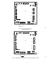
Inverter
The inverter is located inside the control box. This is an air--cooled
device that communicates with the control board and drives the
compressor to the demanded RPM. When the contactor closes, it
powers the inverter with line voltage. The inverter converts the line
voltage to 410 volts DC. The inverter then converts DC voltage
into 3--phase variable frequency and variable voltage.
NOTE: Manually closing the contactor will not cause the unit to
operate. The unit must be operated with an Evolution Control. A
standard thermostat will allow operation only in the emergency
mode (high speed heating or cooling).
Motor Control Drive
(Inverter):
S Converts the sinusoidal AC input mains voltage into a variable
frequency AC output generated used PWM modulation of the
output.
S Drive adjusts the output voltage to run the compressor at the
correct speed at any load point in the envelope.
S The drive actively controls the motor current to insure the proper
torque is provided for the given loading condition.
S The drive control algorithms insure the magnetic field set up in
the motor is synchronized with the rotor insuring smooth
efficiency operation.
S The drive actively controls the input current at heavy loading
conditions to insure the input power factor to the drive is >0.95.
Variable Speed Compressor
This unit contains a variable speed compressor that has a wide
operating range. This compressor can only be operated by the
specific inverter supplied with the unit.
Motor Control Drive + BPM
together:
S Through the combination of the drive and motor, the
system is able to operate over a wide speed range.
S The drive provides protection of the system to various
abnormal conditions including limiting the compressor
envelope of operation to appropriate boundaries.
S Provides many pieces of system data as feedback to the
system controller.
S Allows operation at least than full performance in case of
system faults or issues.
EQUIPMENT DAMAGE HAZARD
Failure to follow this caution may result in equipment damage
and/or improper operation.
Do not attempt to apply line voltage directly to the
compressor. This will destroy the compressor.
CAUTION
!
Compressor Brush--less Permanent Magnet Motor (BPM):
S The motor inductance reacts to the drive current and a sinusoidal
current is induced through the motor windings.
S The sinusoidal current sets a rotating magnetic field, at the
frequency set by the drive.
S The magnets enable the motor to synchronize to that frequency,
set by the drive.
S Suppliesthemechanicalpower afforded toitby thedrivevoltage,
current and frequency.
Electronic Expansion Valve (EXV)
This unit uses an electronic expansion valve for refrigerant
metering in the heating mode. The control board drives the EXV to
its proper position based on the operating mode and conditions.
The Evolution Control Service mode allows for manual opening
and closing of the EXV for troubleshooting and pump down.
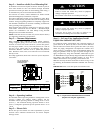
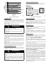
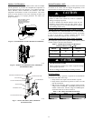
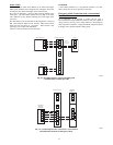
Field control Connections
For normal operation use the ABCD Evolution connections only.
Only two wires, AB arerequired. See Fig. 18. Discrete inputs (Y,C,
O) are available for emergency operation if the Evolution Bus is
not in operation.
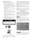
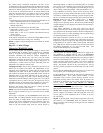
Pressure Transducer (SPT)
A 5 VDC output low pressure transducer that provides a 0--5 VDC
data for interpretation by the control board for a 0 to 200 psig
range of pressure at the suction tube. This interpreted pressure data
is then intelligently used by the control board for low pressure
cut--out, loss of charge management, compressor overall envelope
management, oil circulation management, lubrication management
and EXV control. (See Fig. 17.)
Compressor Control Contactor
The contactor has a 24 volt coil. The electronic control board
controls the operation of the contactor.
TROUBLESHOOTING
Systems Communication Failure
If communication with the Evolution control is lost with the User
Interface (UI), the control will flash the appropriate fault code (see
Table 7). Check the wiring to the User Interface and the indoor and
outdoor units and power.
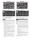
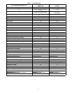
Model Plug
Each control board contains a model plug. The correct model plug
must be installed for the system to operate properly (see Table 3).
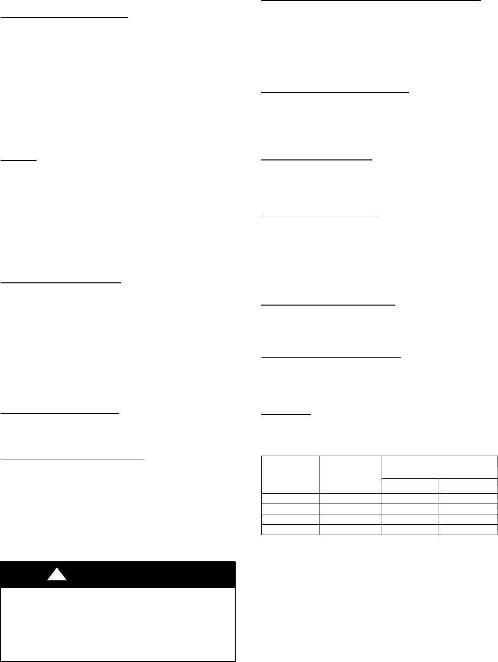
Table 3 – Model Plug Information
MODEL
NUMBER
MODEL PLUG
NUMBER
PIN RESISTANCE
(K --- ohms)
Pins 1 --- 4 Pins 2---3
280ANV024 HK70EZ001 5.1K 11K
280ANV036 HK70EZ002 5.1K 18K
280ANV048 HK70EZ003 5.1K 24K
280ANV060 HK70EZ004 5.1K 33K
The model plug is used to identify the type and size of unit to the
control.
On new units, the model and serial numbers are input into the
board’s memory at the factory. If a model plug is lost or missing at
initial installation, the unit will operate according to the
information input at the factory and the appropriate error code will
flash temporarily. An RCD replacement board contains no model
and serial information. If the factory control board fails, the model
plug must be transferred from the original board to the replacement
board for the unit to operate.
NOTE: The model plug takes priority over factory model
information input at the factory. If the model plug is removed after
initial power up, the unit will operate according to the last valid
model plug installed, and flash the appropriate fault code
temporarily.