


4
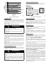
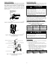
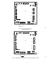
Step 2 — Install on a Solid, Level Mounting Pad
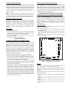
If conditions or local codes require the unit be attached to pad, tie
down bolts should be used and fastened through knockouts
provided in unit base pan. Refer to unit mounting pattern in Fig. 3
to determine base pan size and knockout hole location.
For hurricane tie downs, contact distributor for details and PE
(Professional Engineer) Certification, if required.
On rooftop applications, mount on level platform or frame. Place
unit above a load--bearing wall and isolate unit and tubing set from
structure. Arrange supporting members to adequately support unit
and minimize transmission of vibration to building. Consult local
codes governing rooftop applications.
Roof mounted units exposed to winds above 5 mph may require
wind baffles. Consult the Service Manual -- Residential Split
System Air Conditioners and Heat Pumps Using Puron
Refrigerant for wind baffle construction.
NOTE: Unit must be level to within 2 (3/8 in./ft,9.5 mm/m.)
per compressor manufacturer specifications.
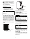
Step 3 — Clearance Requirements
When installing, allow sufficient space for airflow clearance,
wiring, refrigerant piping, and service. Allow 24 in. (609.6 mm)
clearance to service end of unit and 48 in. (1219.2 mm) (above
unit. For proper airflow, a 6--in. (152.4 mm) clearance on 1 side of
unit and 12--in. (304.8 mm) on all remaining sides must be
maintained. Maintain a distance of 24 in. (609.6 mm) between
units. Position so water, snow, or ice from roof or eaves cannot fall
directly on unit.
On rooftop applications, locate unit at least 6 in. (152.4 mm) above
roof surface.
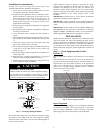
3/8---in.(9.53 mm)Dia.
Tiedown Knockouts in
Basepan(2)Places
ViewFrom Top
A05177
UNITBASE PAN
Dimension in. (mm)
TIEDOWNKNOCKOUTLOCATIONSin. (mm)
A B C
35 X 35
(889 X 889)
9–1/8 (231.8) 6–9/16 (166.7) 28–7/16 (722.3)
Fig. 3 -- Tiedown Knockout Locations
Step 4 — Operating Ambient
The minimum outdoor operating ambient in cooling mode is 55_F
(12.78_C) without low ambient cooling enabled, and the
maximum outdoor operating ambient in cooling mode is 125_F
(51.67_C). The maximum heating operation ambient is 66_F
(18.9_C). Compressor protections prevent operation below --10 to
-- 2 0 _F.
Step 5 — Elevate Unit
Elevate unit per local climate and code requirements to provide
clearance above estimated snowfall level and ensure adequate
drainage of unit.
CAUTION
!
UNIT OPERATION HAZARD
Failure to follow this caution may result in equipment
damage or improper operation.
Do not allow water and/or ice to build up in base pan.
CAUTION
!
UNIT OPERATION HAZARD
Failure to follow this caution may result in equipment
damage or improper operation.
Locate the unit in such a way that it is stable in all
circumstances including adverse weather conditions.
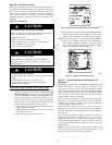
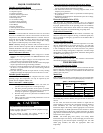
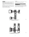
Step 6 — In Long--Line Applications, Install
Liquid--Line Solenoid Valve (LSV)
For refrigerant piping arrangements with equivalent lengths of
greater than 80 ft. (24.38 m) and/or when elevation difference
between indoor and outdoor unit is greater than 20 ft. (6.10 m),
follow the piping configuration and liquid line solenoid valve
(LSV) accessory requirements from the Residential Piping and
Long--line guideline. CCH, start gear and piston changes do not
apply. If required by Long--Line Guideline, install LSV kit, part
no. KHALS0401LLS, specifically designed for Puron refrigerant
heat pumps. LSV should be installed within 2 ft. (0.61 m) of
outdoor unit with flow arrow pointing toward outdoor unit.
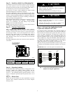
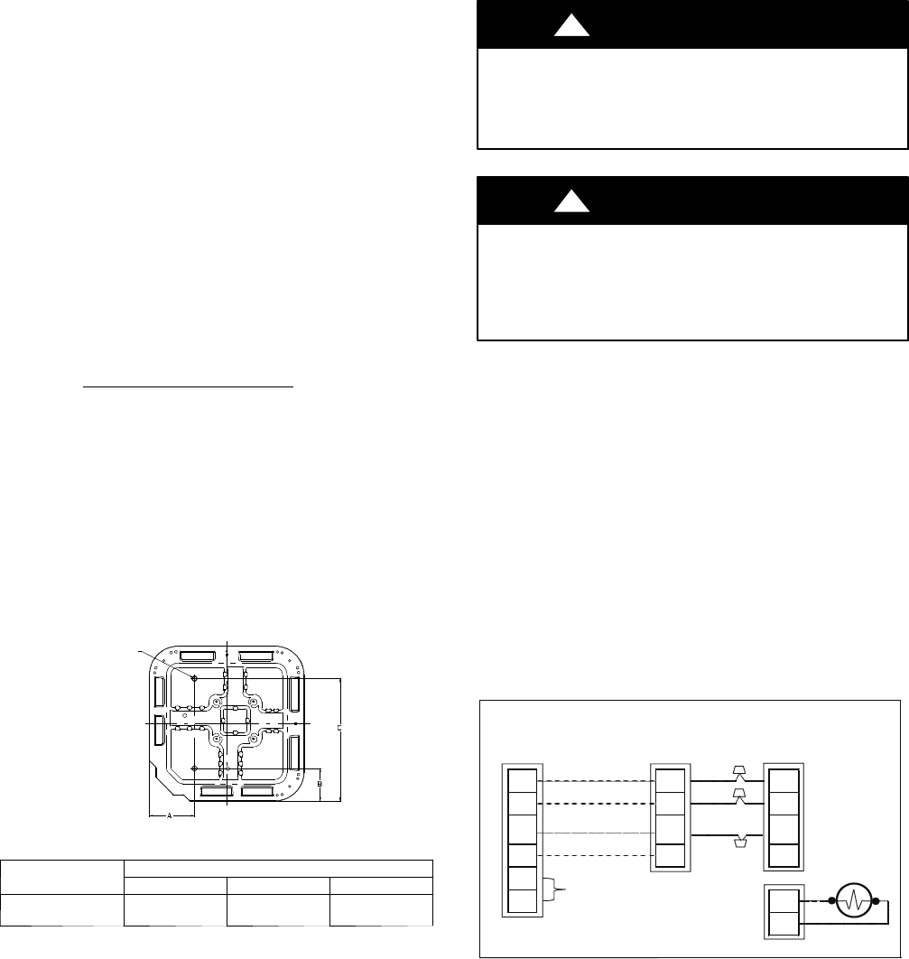
Make the necessary electrical connections as shown on Fig. 21 and
by following the Installation Instructions included with accessory
kit.
IMPORTANT: Flow arrow must point toward outdoor unit.
Green
Yellow
White
ABCD
Connection (optional)
Red
LLS
LS
User Interface
Optional Remote
Room Sensor
Furnace or
Fan Coil
Variable
Speed
HP
A
B
C
C
S2
A
B
C
D
A
B
C
D
S1
No
Use
A12053
Fig. 4 -- Liquid Line Solenoid Electrical Connection
(Required for long line applications)