


3
Installation Recommendations
In some cases noise in the living area has been traced to gas
pulsations from improper installation of equipment.
1. Locate unit away from windows, patios, decks, etc. where
unit operation sound may disturb customer.
2. In noise sensitive applications (such as bedrooms), when a
lineset is mounted to ceiling joists or floor joists, the out-
door unit must be located at least 10 ft (3.05 m) away. If
this is not possible, create a line set configuration with
enough bends to provide 10 ft (3.05 m) of total line set
length outside the dwelling
3. Ensure that vapor and liquid tube diameters are appropriate
for unit capacity.
4. Run refrigerant tubes as directly as possible by avoiding un-
necessary turns and bends.
5. Leave some slack between structure and unit to absorb vi-
bration.
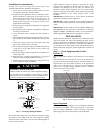
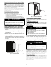
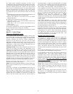
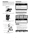
6. When passing refrigerant tubes through the wall, seal open-
ing with RTV or other pliable silicon--based caulk (see Fig.
1).
7. Avoid direct tubing contact with water pipes, duct work,
floor joists, wall studs, floors, and walls.
8. Do not suspend refrigerant tubing from joists and studs with
a rigid wire or strap which comes in direct contact with
tubing (see Fig. 1).
9. Ensure that tubing insulation is pliable and completely sur-
rounds vapor tube.
10. When necessary, use hanger straps which are 1 in. wide and
conform to shape of tubing insulation. (See Fig. 1.)
11. Isolate hanger straps from insulation by using metal sleeves
bent to conform to shape of insulation.
EQUIPMENT DAMAGE HAZARD
Failure to follow this caution may result in equipment damage.
If proper lineset routing techniques are not followed, variable
speed systems can be susceptible to lineset transmitted noise
inside the dwelling and, in extreme cases, tubing breakage.
CAUTION
!
INSULATION
SUCTION TUBE
LIQUID TUBE
OUTDOOR WALL INDOOR WALL
LIQUID TUBE
SUCTION TUBE
INSULATION
CAULK
HANGER STRAP
(AROUND SUCTION
TUBE ONLY)
JOIST
1” (25.4 mm)
MIN
THROUGH THE WALL
SUSPENSION
A07588
Fig. 1 -- Connecting Tubing Installation
The outdoor unit contains the correct amount of refrigerant charge
for operation with AHRI rated and factory--approved smallest
indoor unit when connected by 15 ft (4.57 m) of field--supplied or
factory accessory tubing.
Adjust refrigerant charge by adding or removing the charge
to/from the unit depending on lineset length and indoor unit as
calculated and displayed on the UI. The user interface (UI)
calculates required charge adjustment and total system charge
required. For proper unit operation, check refrigerant charge using
charging information in the Check Charge section of this
instruction.
IMPORTANT: Liquid--line size is 3/8--in. OD for all 280ANV
applications including long line applications.
IMPORTANT: Always install the factory--supplied liquid--line
filter drier. Obtain replacement filter driers from your distributor or
branch.
IMPORTANT: Always install the factory--supplied muffler (part
#LM10KK003) on the vapor line as described in the
Factory
Supplied Muffler Installation
section of these instructions.
Obtain replacement mufflers from you distributor or branch.
INSTALLATION
Specifications for this unit in residential new construction market
require the outdoor unit, indoor unit (including metering device),
refrigerant tubing sets, and filter drier, and muffler listed in pre--sale
literature. There can be no deviation. Consult the Service Manual –
Air Conditioners and Heat Pumps Using Puron Refrigerant to
obtain required unit changes for specific applications and for R--22
retrofit.
Step 1 — Check Equipment and Job Site
Unpack Unit
Move to final location. Remove carton taking care not to damage
unit.
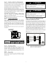
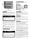
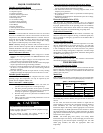
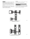
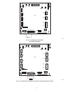
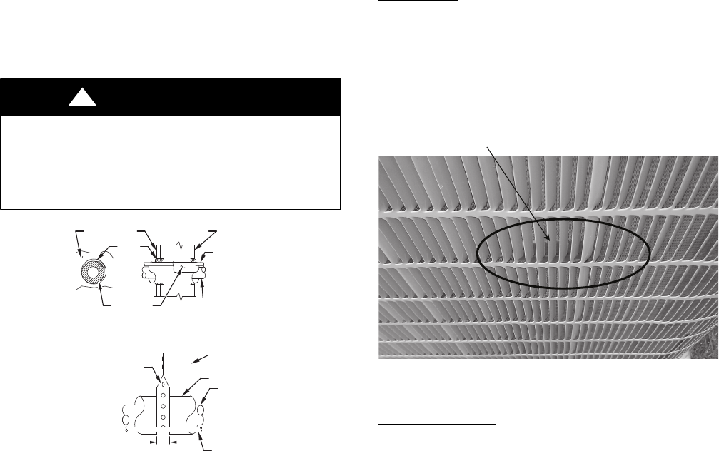
This unit employs one louver spacer on each of the four sides to
prevent louver movement during operation. Thelouver spacers are
trapped between the coil surface and louver at the approximate
center of each side (See Fig. 2). This louver spacer should be
present and, if dislodged during shipment, must be reinstalled
before unit is placed into operation.
Louver Spacer
A11380
Fig. 2 -- Louver Spacer Location
Inspect Equipment
File claim with shipping company prior to installation if shipment
is damaged or incomplete. Locate unit rating plate on unit corner
panel. It contains information needed to properly install unit.
Check rating plate to be sure unit matches job specifications.