13
Pressure Switch Protection
The outdoor unit is equipped with high pressure switch. If the
control senses the opening of a high pressure switch, it will
respond as follows:
1. De--energize the contactor.
2. Keep the outdoor fan operating for 15 minutes.
3. Display the appropriate fault code (see Table 7).
4. After a 15 minute delay, if thereis a call forcooling or heat-
ing and HPS is reset, the contactor is energized.
5. If HPS has not closed after a 15 minute delay, the outdoor
fan is turned off. If the open switch closes anytime after the
15 minute delay, then resume operation with a call for cool-
ing or heating at a temporary reduced capacity.
6. If HPS trips 3 consecutive cycles, the unit operation is
locked out for 4 hours.
7. In the event of a high--pressure switch trip or high--pressure
lockout, check the refrigerant charge, outdoor fan operation,
and outdoor coil (in cooling) for airflow restrictions, or in-
door airflow in heating.
8. In the event of a low--pressure trip or low--pressure lockout,
check the refrigerant charge and indoor airflow (cooling)
and outdoor fan operation and outdoor coil in heating.
Control Fault
If the outdoor unit control board has failed, the control will flash
the appropriate fault code (see Table 7). The control board should
be replaced.
Brown--Out Protection
If the line voltage is less than 187v for at least 4 seconds, the
contactor and fan relay are de--energized. Compressor and fan
operation are not allowed until voltage is a minimum of 190v. The
control will flash the appropriate fault code (see Table 7).
230V Line (Power Disconnect) Detection
If there isno 230v at the contactor when the indoor unit is powered
with a cooling or heating demand, the appropriate fault code is
displayed. Verify the disconnect is closed and 230v wiring is
connected to the unit.
Inverter Voltage Sensing
The control board senses thepresence or absence of230 V through
the feedback from inverter. The control monitors the high voltage
to the inverter. Voltage should be present anytime the contactor is
energized and voltage should not be present when the contactor is
de--energized.
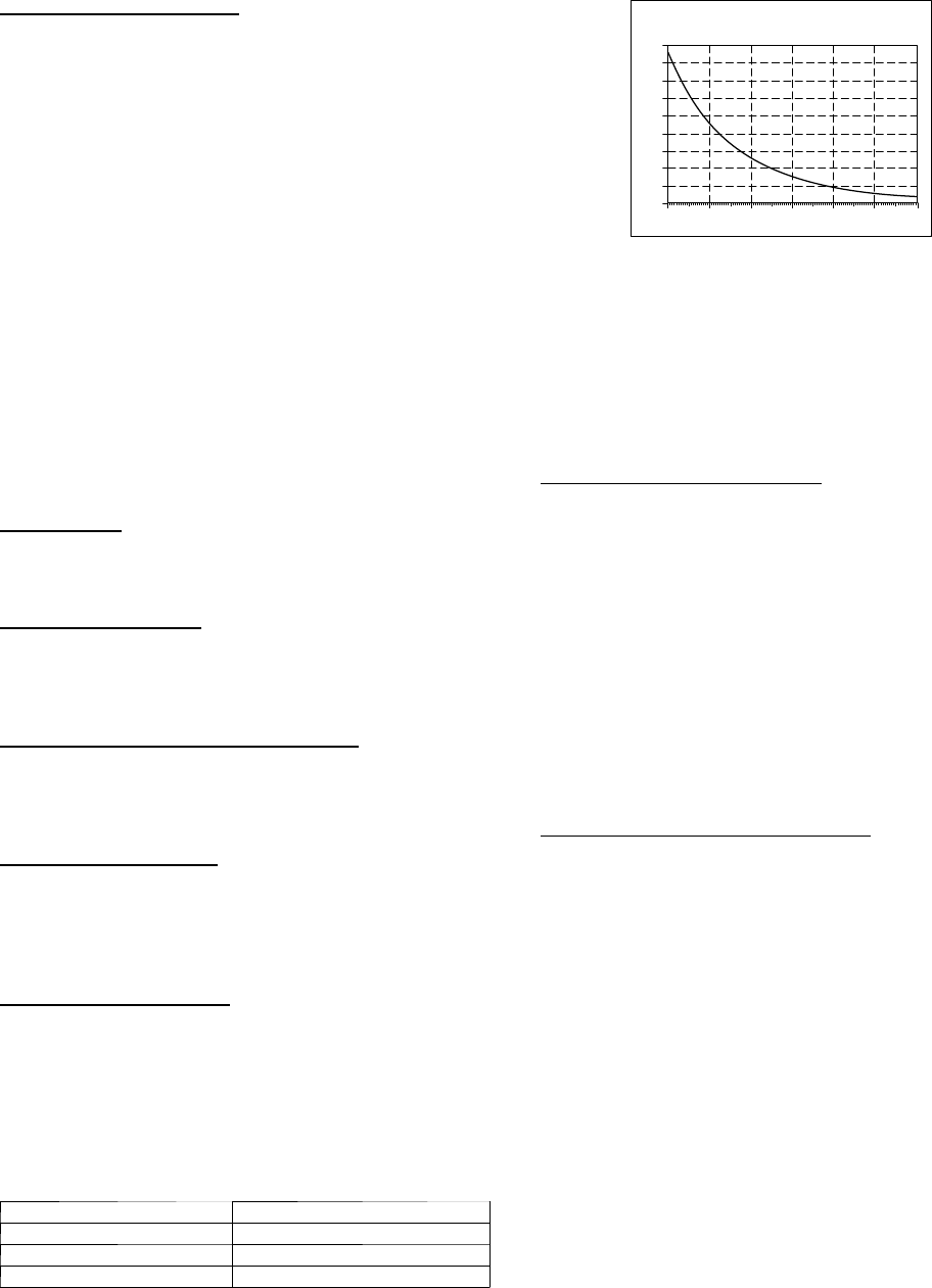
Temperature Thermistors
Thermistors are electronic devices which sense temperature. As the
temperature increases, the resistance decreases. Thermistors are
used to sense outdoor air (OAT), coil temperature (OCT) and the
suction line thermistor (OST) located between the reversing valve
and the accumulator.
Refer to Table 4 and Fig. 14 for resistance values versus
temperature.
Table 4 – Resistance Values versusTemperature
TEMPERATURE RESISTANCE (ohms)
25.0°C (77.0°F) 10.0 + /- 2.3%
0.0°C (32.0°F) 32.6 + /- 3.2%
-28.0°C (-18.4°F) 85.5 + / -3.4%
0
10
20
30
40
50
60
70
80
90
0 20 40 60 80 100 120
TEMPERATURE (DEG. F)
RESISTANCE (KOHMS)
THERMISTOR CURVE
A91431
Fig. 14 -- Thermistor Resistance Versus Temperature
If the outdoor air or coil thermistor should fail, the control will
flash the appropriate fault code (see Table 7.)
IMPORTANT: The outdoor air thermistor, coil thermistor and
suction thermistor should be factory mounted in the final
locations. Check to ensure thermistors are mounted properly
(See Fig. 15, 16 and 17).
Thermistor Sensor Comparison
The control continuously monitors and compares the outdoor air
temperature sensor and outdoor coil temperature sensor to ensure
proper operating conditions. The comparison is:
S In cooling if the outdoor air sensor indicates 10_F( 5.6_C)
warmerthan thecoilsensor (or) theoutdoor airsensorindicates
20_F( 11_C) cooler than the coil sensor, the sensors are out of
range.
S In heating if the outdoor air sensor indicates 35_F( 19.4_C)
warmerthan thecoilsensor (or) theoutdoor airsensorindicates
10_F( 5.6_C) cooler than the coil sensor, the sensors are out of
range.
If the sensors are out ofrange, the control will flash the appropriate
fault code as shown in Table 7.
The thermistor comparisons are not performed during low ambient
cooling or defrost operation.
Failed Thermistor Default Operation
Factory defaults have been provided in the event of failure of
outdoor air thermistor (OAT) and/or outdoor coil thermistor
(OCT).
If the OAT sensor should fail, low ambient cooling will not be
allowed and the one--minute outdoor fan off delay will not occur.
Defrost will be initiated based on coil temperature and time.
If the OCT sensor should fail, low ambient cooling will not be
allowed. Defrost will occur at each time interval during heating
operation, but will terminate after 5 minutes.
If there is a thermistor out--of--range error, defrost will occur at
each time interval during heating operation, but will terminate after
5 minutes.
Count the number of short and long flashes to determine the
appropriate flash code. Table 7 gives possible causes and actions
related to each error.


