


5
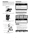
Step 7 — Make Piping Connections
!
WARNING
PERSONAL INJURY AND UNIT DAMAGE
HAZARD
Failure to follow thiswarning could result in personal injury or
death.
Relieve pressure and recover all refrigerant before system
repair or final unit disposal. Use all service ports and open all
flow--control devices, including solenoid valves.
CAUTION
!
UNIT DAMAGE HAZARD
Failure to follow this caution may result in equipment
damage or improper operation.
Do not leave system open to atmosphere any longer than
minimum required for installation. POE oil in compressor is
extremely susceptible to moisture absorption. Always keep
ends of tubing sealed during installation.
CAUTION
!
UNIT DAMAGE HAZARD
Failure to follow this caution may result in equipment
damage or improper operation.
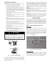
If ANY refrigerant tubing is buried, provide a 6 in. (152.4
mm) vertical rise at service valve. Refrigerant tubing lengths
up to 36 in. (914.4 mm) may be buried without further
special consideration. Do not bury lines longer than 36 in.
(914.4 mm).
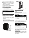
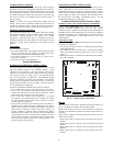
Outdoor units may be connected to indoor section using accessory
tubing package or field--supplied refrigerant grade tubing of correct
size and condition. For tubing requirements beyond 80 ft. (24.38
m), substantial capacity and performance losses can occur. Follow
the pipe sizing recommendations in the 280ANV Product data to
manage these losses.
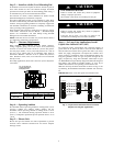
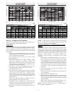
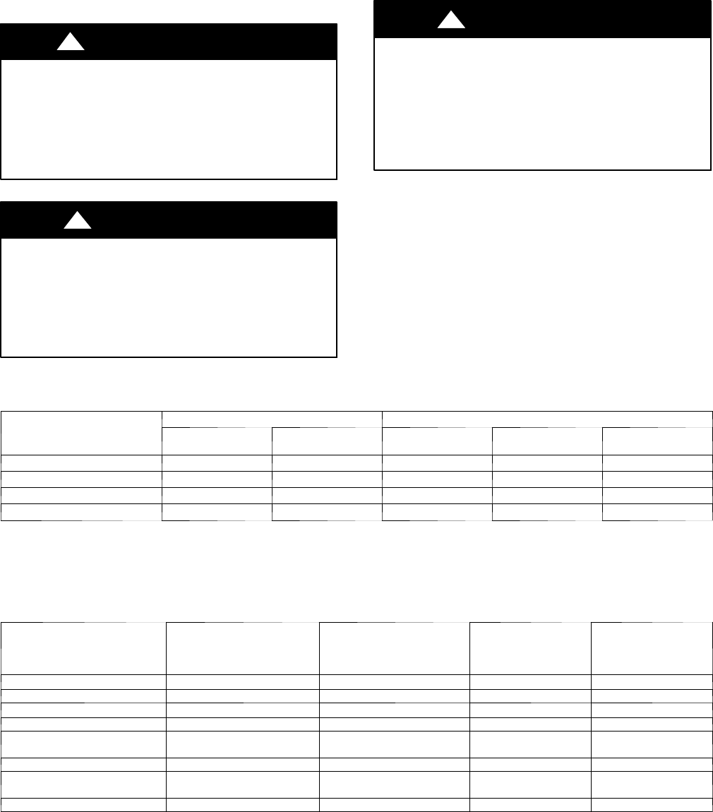
Refer to Table 1 for field tubing diameters. Refer to Table 2 for
accessory requirements.
Table 1 – Refrigerant Connections and Recommended Liquid and Vapor Tube Diameters (in.)
UNIT SIZE
LIQUID VAPOR*
Connection
Diameter
Tube
Diameter
Connection
Diameter
Max (Rated)
Diameter
Minimum Tube
Diameter
280ANV024
3/8 3/8 7/8 7/8 5/8
280ANV036
3/8 3/8 7/8 7/8 5/8
280ANV048
3/8 3/8 7/8 1 --- 1/8 3/4
280ANV060
3/8 3/8 7/8 1 --- 1/8 3/4
* Unitsare rated with 25ft. (7.6 m) oflineset.See Product Data sheet for performance data when using different size and length line sets.
Notes:
1. Donot applycapillarytube indoorcoils totheseunits.
2. For Tubing Set lengths between 80 and 200 ft.( 24.38 and 60.96 m) horizontal and / orgreater than 20 ft. (6.1 m) vertical differential, an accessory Liquid Line
Solenoidmustbe installed.
Table 2 – Accessory Usage
ACCESSORY
REQUIREDFOR
LOW--- AMBIENT COOLING
APPLICATIONS
(Below55F/12.8_C)
REQUIRED FOR LONG LINE
APPLICATIONS*
(Over 80 ft/24.38 m)
REQUIRED FOR SEA
COAST APPLICATIONS
(Within 2 miles/3.22 km)
Installations withR adio
Frequency Interference
Concerns in the Range
of2to30MHZ
Crankcase Heater Standard
Standard
Standard Standard
Evaporator Freeze Protection Standard with Evolution Control No No No
Liquid---Line Solenoid Valve No
Yes
No No
Low---Ambient Control Standard with Evolution Control No No No
Puron Refrigerant Balance Port
Hard ---ShutOff TXV
Yes{
Yes{
Yes{ Yes{
SupportFeet Recommended No Recommended No
WinterStartControl
Standardwith Evolution
Control
Standardwith Evolution
Control
Standardwith Evolution
Control
Standardwith Evolution
Control
EMI Kit No No No Yes
* For tubing setlengths between 80 and200 ft. (24.38 and 60.96m) horizontal or 20 ft. (6.10 m) vertical differential (total equivalent length), an accessory
Liquid Line Solenoid must be installed.
{ Required on all indoorunits. Standardon all new Puronrefrigerantfan coilsand furnacecoils.
Standard =Standard for all new Puron refrigerant fancoilsand furnace coils.