59
With the power off, you can check the continuity through the surge protector. Place a meter lead on the
top pin #1 of the surge protector and pin #3 on the bottom of the surge protector. Check across the top
pin #3 and the bottom pin #1. If you read continuity across these two points, the surge protector is good.
If you do not get continuity, replace the surge protector.
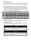
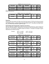
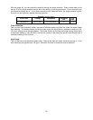
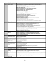
Table 26. Remote Controls.
Wire Color Voltage Resistance
Connector
No.
Pin
Nos.
Terminals B1 10-13 VDC 1.5-3.0k ohms B 1-3
Frost Protection:
This unit has frost protection heaters mounted at different points to protect the water the water heater
from freezing. The heaters located on the hot water outlet line should have a resistance reading of 180-
207 ohms through each of these heaters. The heater located on the heat exchanger piping should have
a resistance reading of 156-180 ohms, and the one located in the water flow sensor valve should have a
resistance reading of 24-28 ohms.
Amp Fuses:
This unit has two inline three-amp glass fuses. Remove the fuse and check continuity through it. If you
have continuity through the fuse, it is good. Otherwise, the fuse is blown and must be replaced.


