


40
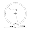
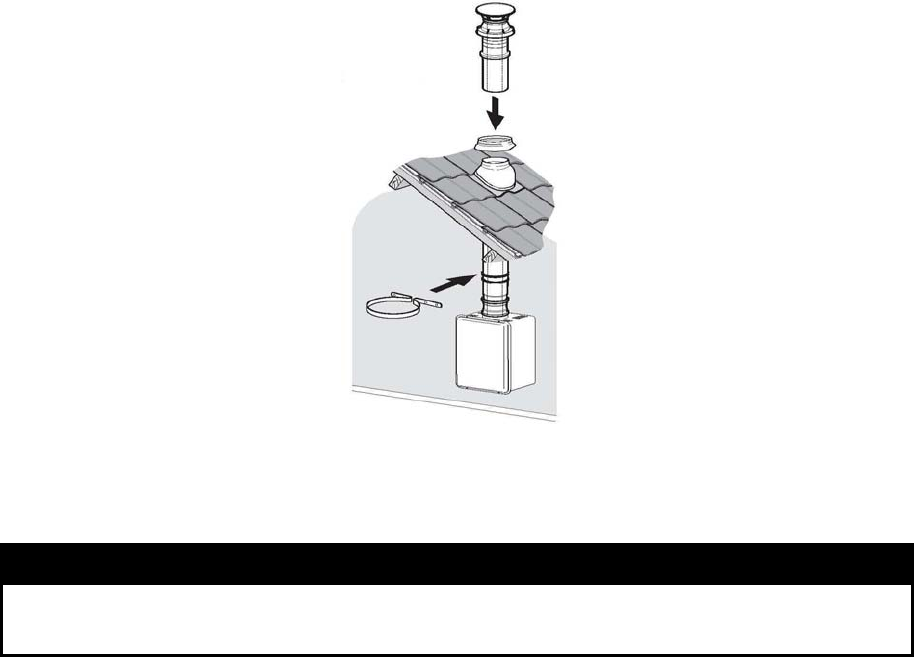
Mounting the Vent System – Vertical Discharge
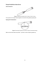
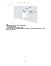
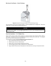
Figure 34. Illustration Showing the Installation of Vertical Discharge Venting.
Vent connections must be firmly pressed together, so that the gaskets form an airtight seal. Secure the
system with a vent pipe clamp or perforated hanger iron.
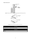
NOTE
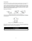
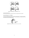
When the total vent system length is greater than 5 ft (1.52 m), condensate will form, which could
damage the water heater. For vent lengths greater than 5 ft (1.52 m), the condensate collector and
a trap must be used.
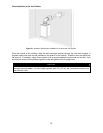
Direct Vent Installation – TG-237I Models Only
The air intake systems consists of field supplied 4 in. diameter stainless steel, Schedule 40 PVC, ABS, or
CPVC pipe. A maximum of 6 ft of semi-rigid flexible aluminum ducting can also be used. Foil wrapped
dryer vent and cell core products are not authorized.
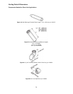
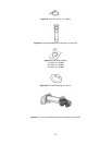
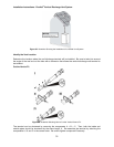
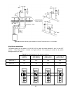
To Connect the Air Intake (See Error! Reference source not found. 35):
1. Drill (2) small holes at the end of the air intake.
2. Slide the pipe over the air intake terminal.
3. Using a level, ensure the pipe is straight up and down.
4. With self tapping screws, attach the pipe to the air intake terminal.
5. Apply a bead of silicone around the pipe and air intake terminal, ensuring an air tight connection.