


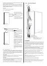
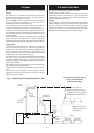
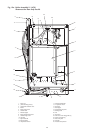

Heating return
Non return
valve
Non return
valve
Hose union
Test cock
Temporary hose
Stop cock
Auto
air vent
Heating return
Stop
cock
Fill point
Non return
valve
Make up
vessel
1200mm (48 in)
above the highest
point of the system.
9
Note:
A drain cock
should be fitted
at the lowest
point of the
heating circuit
and beneath
the appliance
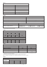
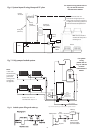
Fig. 7. Fully pumped sealed system.
RV
LV
LV
RV
RV
RV
LV
LV
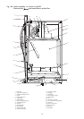
INDIRECT
CYLINDER
APPLIANCE
Heating Return
Heating Flow
Cylinder Return
Hot Water Flow
BS
Stop Valve Fixed Cylinder Type or sealed systems - Approved connection
Mains Cold Water
Radiator Valve - Flow RV
Lockshield Valve - Return LV
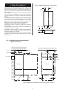
Expansion
Vessel
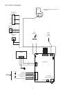
For system
wiring
please refer to
Fig. 10. and the
controls
manufacturers
details.
Bypass
balancing valve or
bathroom
radiatior with two
lockshield valves
Pressure
Gauge
Relief
Valve
Fig. 8. Sealed system filling and make-up.
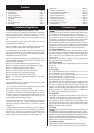
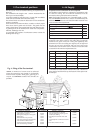
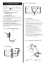
Primary
cold feed
(15mm min.)
Heating vent
(22mm min.)
Feed and
Vent Cistern
Diverting
valves
Boiler
Pump
Radiator
S.H. – Minimum static head 1.2m
measured from the highest point in the
heating system (top surface of the appliance
or highest point in the heating system) to the
water level in the feed and expansion tank
N.B. A drain cock should be
installed at the lowest point of
the heating circuit
Domestic hot
water cylinder
S.H.
S.H.
150mm max
Fig. 6. System layout if using Honeywell 'S' plan
For system wiring please refer to
Fig. 10. and the controls
manufacturers details.
Bypass or
uncontrolled
radiator