


Important: Turn off the gas and electricity supplies and drain,
where necessary, before replacing any components.
15.1 Always check for gas soundness where relevant and carry
out functional checks as described in Section 12 Commissioning.
Any O-ring, gasket or seal that appears damaged must be
replaced.
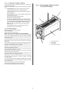
15.2 Component Access
Refer to Section 14.3 Inspection and Servicing for access to
components.
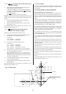
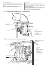
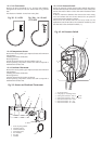
15.3 Draining the Appliance
Isolate the appliance.
Remove the casing. Refer to Section 14.3.
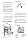
Fit a tube to the drain connection from the system (top connection
only) and open the tap. Refer to Fig 34. Close the tap when the flow
has stopped.
IMPORTANT: A small quantity of water will remain in some
components. Protect any electrical components when removing
items that might retain water.
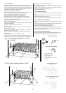
15.4 Component Replacement
Replace any components removed from the appliance in the
reverse order using new gaskets/O-rings/sealant/heat transfer
paste where necessary. Always check that any electrical
connections are correctly made and that all screws are tight.
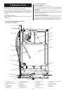
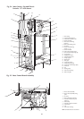
15. Replacement Of Parts
26
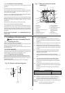
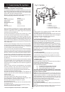
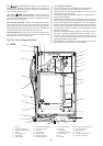
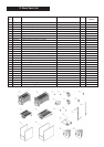
1. Inner case 8. Base/controls fixing screw
2. J bolts and wing nuts (2) 9. Cabinet fixing screw
3. Combustion chamber cover 10. Gas valve
4. Burner 11. Spark electrode
5. Burner fixing screw 12. Burner injector
6. Control knob 13. Temperature sensor
7. Indicator lights 14. Overheat thermostat
15. Air pressure switch 22. Inner case cover fixing points (4)
16. Flow pipe 23. Flue hood
17. Return pipe 24. Outer case earth tag
18. Combustion test point 25. Side cover plate
19. Sensing tubes 26. Wire clip
20. Fan 27. Front baffle
21. Fan clamp (2 screws)
Fig. 33b. Inner Casing and control
14/19 and 19/24CBi
1
2
23
22
3
4
5
6
7
8
9
10
11
12
13
14
15
16
17
18
19
20
21
24
25
27
26