working at a gauge pressure of at least 0.35bar above the relief
valve setting if on a sealed system.
Where a storage system will not have a vent to atmosphere the
installation must comply with Building Regulations and Water
Company bye-laws. If connecting to an existing system the local
authority should be informed.
2.7 Flue
There are 3 fluing options available.
(i) Rear Only Flue Kit.
(ii)
Multi-Directional Horizontal Flue Kit.
(iii) Vertical Flue Kit
A vertical flue option is also available with flue lengths from
1.1m (without cutting) to a maximum of 3.35m (19/24CBi) or
4.1m (9/14 and 14/19CBi). Optional 45° and 90° bends are
available with this option. NOTE: When using flue bends the flue
length is reduced (see Section11.2.8).
2.8 Controls
A control knob adjusts the boiler temperature, switches the
boiler ON or to STANDBY and acts as a lock-out reset.
2.9 Safety
The appliance must not be operated with the inner casing cover removed.
The gas and electricity supplies must be turned off before
servicing or working on the appliance.
The casing is earthed through a push-on connector at the base.
When the casing is refitted this connection MUST be remade.
3
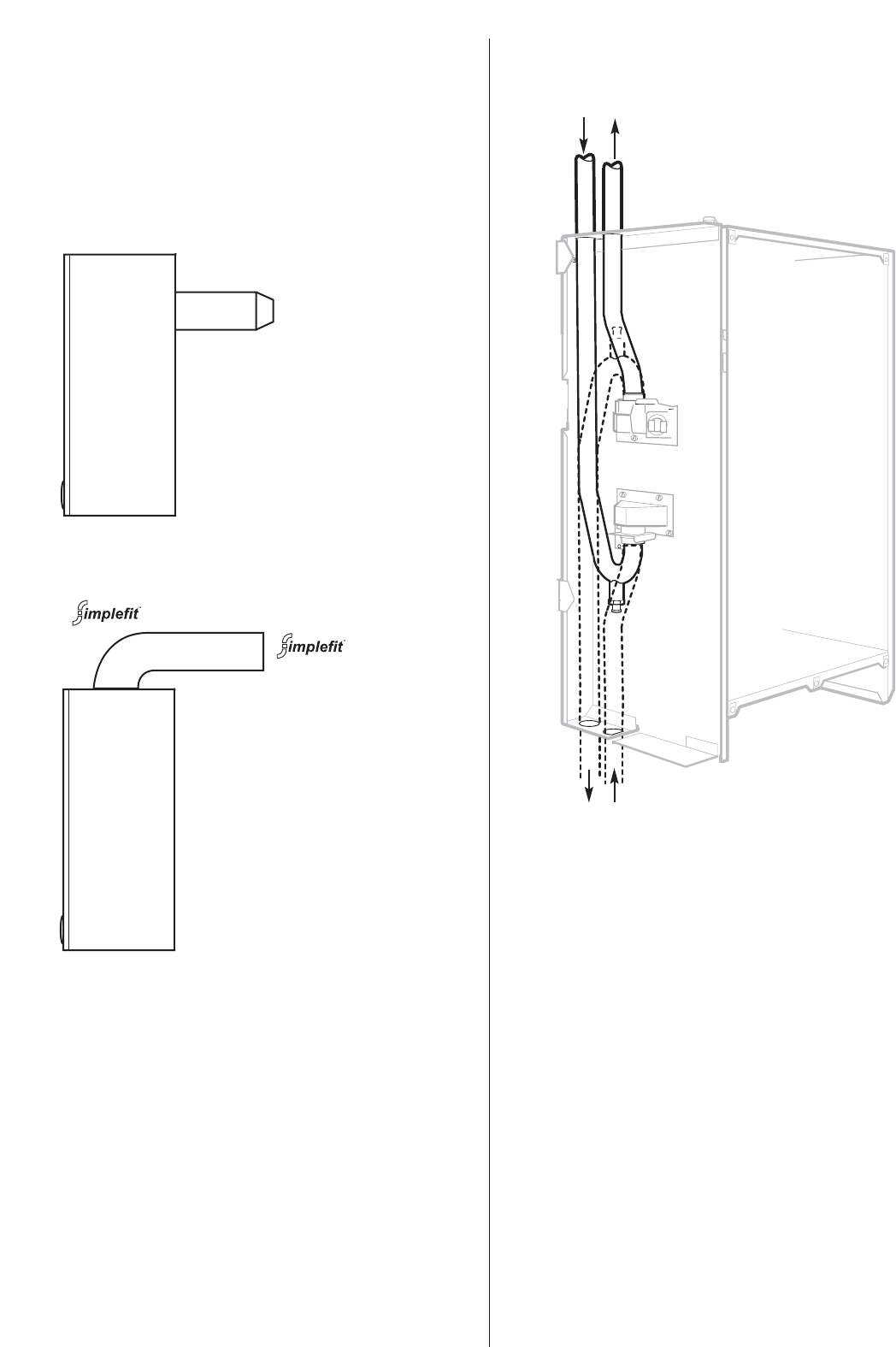
Fig. 1. Water flow diagram.
Pipes
Return Flow
Alternative position
of Flow and Return pipes
NOTE: Flow pipe is at the rear
in the alternative position.
2.10 Operation
Central Heating
A demand for heat will ignite the burner. The temperature is
controlled by the integral sensor. At the end of the demand the
burner will go out and the pump will continue to run for up to 4
minutes and the fan for 1 minute to dissipate the residual heat.
Domestic Hot Water:
The supply of domestic hot water depends upon the type of hot
water equipment installed and the control system.
The use of unvented cylinders must be in accordance with the
manufacturers instructions and relevant to British Standards.
The boiler is despatched from the factory with the flow and
return pipework prepared for top outlet connection.
The pipework can be orientated to allow connection from the
bottom by simply unplugging the bayonet style pushfit connec-
tions.
NOTE: When changing from a top connection to one at the bot-
tom the pipe functions are reversed.
Top flow pipe becomes the bottom return pipe.
Top return pipe becomes the bottom flow pipe.
The drain off point on the return pipe becomes an air vent if the
pipes are reversed. In this case a drain point should be fitted
close to the appliance.
Flue can be fitted within
the height of the casing from
220mm to 375mm without
cutting.
The minimum length is
100mm with cutting.
No flue bends or extensions
can be fitted to this system.
Side view
Side view
Flow Return
Standard Flue Kit
can be adjusted from
425mm to 725mm without
cutting.
The minimum length is 250
mm with cutting.
Extended flue lengths upto
a maximum of 2.5m
(19/24CBi) and 3.0m (9/14
and 14/19CBi) are available.
Optional 45° and 90° flue
bend kits are available
NOTE: When using flue
bends the maximum flue
length is reduced (see
Section 11.2.8).
If access to the flue is a
problem then this option
combined with an internal
flue fixing kit should be
used.


