


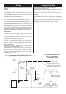
NOTE: READ THIS SECTION FULLY BEFORE COMMENCING THE
INSTALLATION
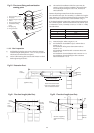
To install a boiler with a rear only flue refer to Section 11.1.
To install a boiler with a telescopic horizontal flue kit refer
to Section 11.2.
To install a boiler with a vertical flue refer to Section 11.2. and the
literature with the flue kit.
11. Installation of the Boiler with a
Rear Only Flue Kit
11.1 Unpacking the Boiler
Check the contents against the packing list.
Remove the wall mounting template, the mounting plate
assembly and the external flue turret connector and restrictors.
11.1.2 Site Preparation
Check that the correct position for the appliance has been chosen
and that the wall is sound, flat and will support the weight of the
appliance. Refer to Sections 4 & 5 and Tables 4 to 8.
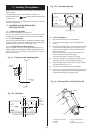
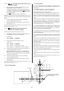
11.1.3 Fixing Holes and Flue Opening
Hold the template to the wall. Check that the template is level.
Mark the position of the fixing holes and the flue opening. Refer to Fig 13.
Mark the position of the bottom fixing point for a screw or
optional security bolt.
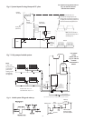
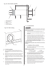
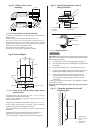
11.1.4 Flue Preparation
(i) Drill the hole for the flue at 110mm diameter.
(ii) Fix the wall-mounting plate - do not fully tighten the
screws.
(iii) Measure the wall thickness L - Min 220mm, Max 375mm.
If L is less than 220mm thick then it is necessary to cut
the flue. To do this subtract L from 220 and cut all flue
parts by this amount.
Ensure that the ducts are square and free from burrs.
Always check dimensions before cutting.
The minimum length L is 100mm with cutting.
(iv) Adjust the telescopic flue assembly to a length L+5mm
and secure with the screw supplied. Refer to Fig. 14.
(v) Apply the plastic tape onto the duct in contact with the
wall (position shown in Fig. 14.).
(vi) Remove the inner flue duct (with the fixing bar).
(vii) Push the outer duct assembly through the wall mounting
plate and wall. Tighten the wall mounting plate fixing
screws after checking that the plate is level.
11. Installing The Appliance
15
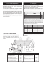
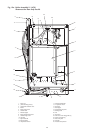
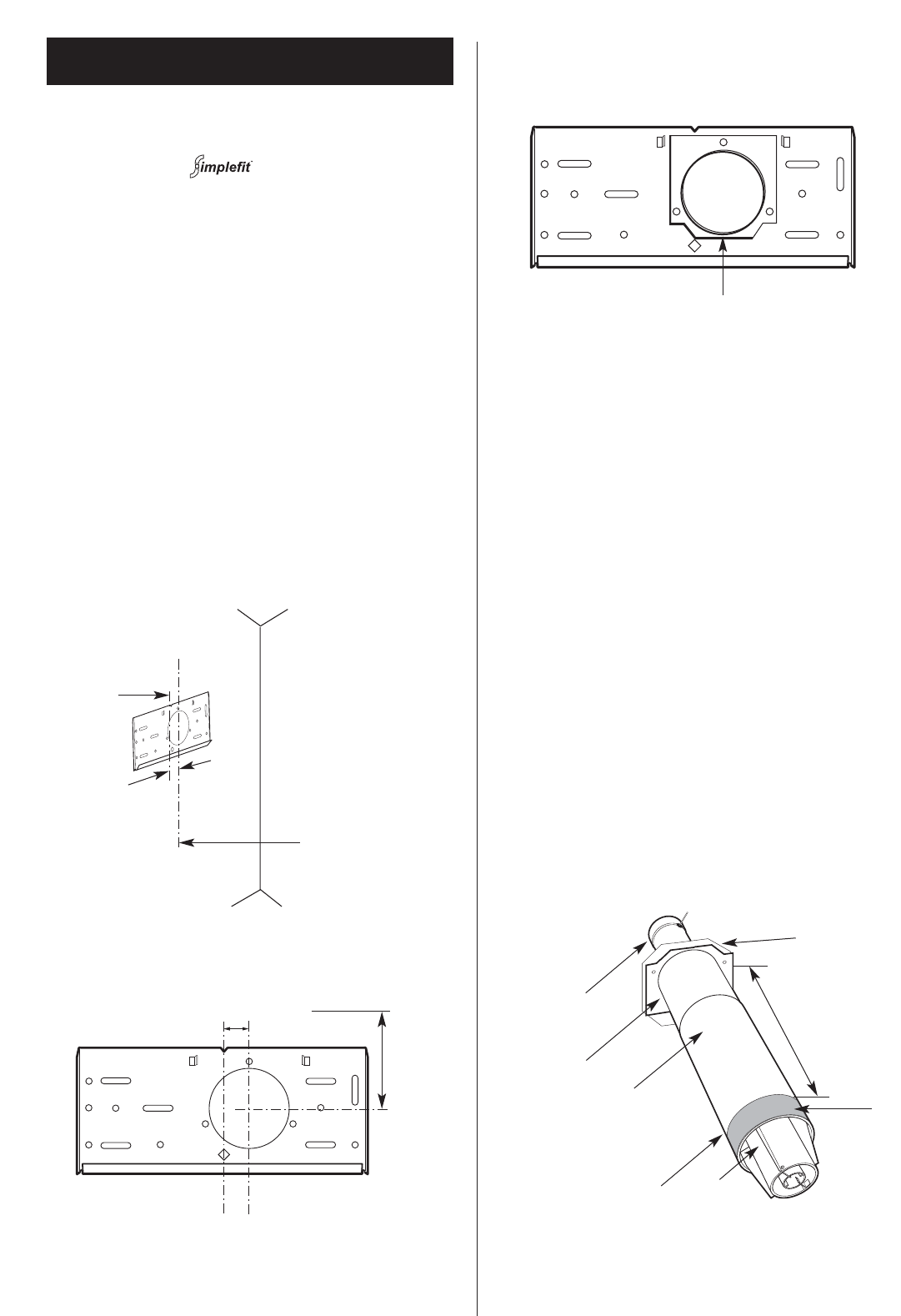
Fig. 14 . Flue assembly - Rear Only Flue Kit
1
1. Telescopic flue assembly
2. Terminal
3. Flange
4. Flue tube with fixing bar
5. Indents
6. Gasket - fitted to inner case
4
3
5
2
L + 5
6
Tape
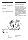
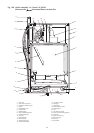
Fig. 13a . Wall plate
36mm
Top of
boiler to
centre of
flue
=142mm
Centre line of flue
Centre line of boiler
Fig. 13b . Flue and wall plate
Flue fixing position
Fig. 13 . Fixing the wall mounting plate.
Centre line
of boiler
Centre line
of flue
36mm