


Cleansing and Inhibiting a Central Heating
Installation in compliance with Benchmark
It is accepted good practice in compliance with BS 7593, Pas 33 and
Benchmark, to cleanse both an existing central heating system when
fitting a replacement boiler, and when fitting a new central heating
system. Then treat with a 'Corrosion Protector.'
Worcester recommend only products from water treatment manu-
facturers participating in Benchmark. These include:
Fernox Sentinel
Alpha-Fry Technologies Betz Dearborn Ltd
Tandem House Foundry Lane
Marlowe Way Widnes
Beddington Farm Road Cheshire
Croydon WA8 8UD
CRO 4XS
Tel: 01799 521133 Tel: 0151 424 5351
Please call either of the above for a specific cleansing method
statement if so required. Below is a general guide for flushing,
which we would advise you to follow along with the chemical
manufacturers recommendations.
Fill up and commission the system in the normal way, i.e: flush
at least once without firing the boiler to remove loose debris.
Then add the cleansing agent, with regard to COSHH, this must
be in the system for a minimum of 1 hour with the system at
normal operating temperature. A longer period of time, up to 48
hours, would be more beneficial to the cleansing process, espe-
cially if heavy sludge deposits are suspected to be present (see
water analysis kit).
Drain the system thoroughly at least twice to remove the cleans-
ing agent and any debris/flux present. This is a crucial part of
the cleansing process and must be done correctly. A TDS meter
is recommended to ensure adequate flushing.
Once you are sure that the system has been cleansed thoroughly,
then add a mixed metal corrosion protector. This will protect
against the formation of scale, corrosion and microbiological
growths. A minimum of one treatment should be added per system.
The label that is supplied by the manufacturer with the corrosion
protector treatment, shall be correctly filled in and attached to
the boiler. Also, the instructions in the Benchmark logbook will
be adhered to.
Please note that the corrosion protector level should be checked
on an annual basis. This is normally done at the time of the
mandatory boiler service. Water analysis test kits and postal
analysis services are available from water treatment suppliers for
this purpose.
Failure to comply with these recommendations, may invalidate
the boiler warranty. If any of the above is unclear, then please
contact The Worcester Technical Services for further advice.
12.1 Remove the outer casing by first loosening the base screw.
Disconnect the earth and lift off the casing.
Check that the electricity and gas supplies to the appliance are
turned off and that all the water connections throughout the
system are tight.
Open any system valves.
Open all the radiator valves. Remove any air vent caps.
If a sealed system has been installed then fill through a WRc
approved filling kit to an initial pressure of 2.5bar.
Check for water soundness throughout the system.
Vent each radiator in turn.
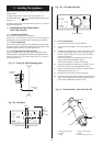
Remove the cap from the pump and turn the shaft about half a
turn. Replace the cap.
Check that the relief valve (sealed system) operates by turning
the knob anti-clockwise until it releases.
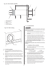
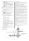
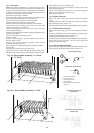
12.2 Set the Expansion Vessel Pressure - Sealed System
The
charge pressure of an expansion vessel is usually 0.5bar, which
is equivalent to a static head of 5m [17ft].
The charge pressure must not be less than the static head at the
point of connection. The expansion vessel must be charged to
0.3bar less than the initial system design pressure.
Note: 1bar = 10.2m = 33.5ft of water.
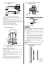
12.3 Set the System Pressure
Fill the system initially until the pressure gauge is at 2.5bar and check for leaks.
Release water through the drain cock until the required system
pressure is obtained, up to a maximum of 1.5bar.
Set the pointer on the pressure gauge to record the set system pressure.
If the pressure indicated on the gauge is greater than 2.65bar
when operating at the maximum central heating temperature,
the expansion vessel is too small and a larger vessel must be fitted.
The boiler with a 10 litre expansion vessel can accommodate a
sealed system volume of about 90 litres. Refer to BS7074 Part 1,
BS5449 and Table 9.
12.4 Clock/Programmer
Any controls fitted to the system should be set up at this stage.
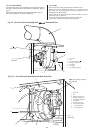
12.5 Check that the gas and electricity supplies are turned off.
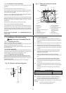
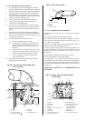
Connect a pressure gauge to the burner pressure test point on
the gas valve. Refer to Fig. 31.
12.6 Light the Boiler
Switch on the gas and electricity supply.
Set the temperature control knob to maximum and any clocks or
programmer to operate continuously.
The gas supply pipe will be purged by the boiler.
The control will work as follows:
(i) Pre-purge (air) for approximately 20 seconds.
(ii) Spark and gas for approximately 5 seconds
(iii) Purge (air) for approximately 10 seconds
The boiler will attempt to light a maximum of 5 times before
going to lockout. To reset the product turn the control knob
fully anti-clockwise and back.
NOTE: The burner pressure is factory set and may be reset to
match the system requirements. If, after checking that the
supply pressure is sufficient i.e. 19 mbar approx [NG] or 36 mbar
approx [PROPANE] at the gas valve inlet pressure test point, the
required pressure cannot be obtained then contact The
Worcester Service Department Tel: 08705 266241.
Reset the pressure as necessary by adjusting the screw on the
gas valve. Refer to Table 1 and Fig.31.
12.7 Domestic Hot Water
Check that the cylinder thermostat, if fitted, is set to between 55°C
and 60°C.
Check that all external controls are calling for heat and that the
flow pipe to the cylinder is hot after a short period.
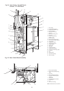
12. Commissioning The Appliance
23
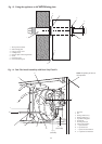
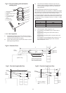
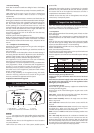
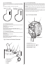
Fig. 31. Gas Valve.
1. Gas valve
2. Solenoids
3. Connector
4. Inlet pressure test point
5. Burner pressure test point
6. Burner pressure adjustment screw
1
2
3
4
5
6
GAS
INLET