


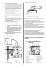
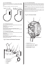
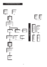

15.4.7 Air Flow Sensor
Remove the fan as described in 14.3. Unscrew and withdraw,
through the fan outlet, the air flow sensor. Refer to Fig .38 and
38a.
The detector is 'handed' - do not force it into place.
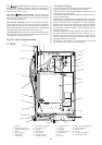
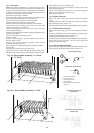
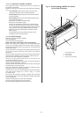
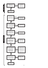
15.4.8 Temperature Sensor
Remove the access panel to give improved access with minimum
side clearance.
Carefully pull-off the connections.
Remove grommet.
Pull off the clip and remove the sensor. Refer to Fig .39.
When replacing component ensure heat sink compound is
added around contact area.
15.4.9 Overheat Thermostat
Remove the access panel to give improved access with minimum
side clearance.
Carefully pull-off the connections.
Remove grommet.
Unscrew and remove the sensor (see above).
When replacing component ensure heat sink compound is
added around contact area.
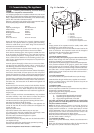
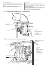
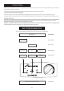
15.4.10 Air Pressure Switch
Noting the position of each pressure tube carefully disconnect
the tubes and electrical connections from the switch. Unclip and
remove the switch if there is more than 50mm clearance. Refer
to Fig.40.
If there is minimum clearance then remove the inner casing
cover and release the two screws. Remove the air pressure
switch and mounting bracket complete.
Ensure that the connections are correctly made on the
replacement switch. Red tube to the connection marked (
+) and
the clear tube to the connection marked (
—).
30
Fig. 39. Sensor and Overheat Thermostat
1. Sensor clip with grommet
2. Temperature sensor
3. Overheat thermostat
4. Thermostat pocket
5. Flow manifold
6. Flow pipe
7. Grommet
1
2
3
4
5
6
7
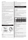
Fig. 40. Air Pressure Switch
1. Air pressure switch
2. Fixing clips (4) - mounting bracket
3. Sensing tube connection - clear to ' ' on fan
4. Sensing tube connection - red to '
+' on fan
5. Electrical connection COM - brown
6. Electrical connection NO - grey
7. Electrical connection NC - white
1
3
2
4
5
6
7
Fig. 38 - 9/14CBi Fig. 38a - 14/19 and
19/24CBi
+
+