


11.2.12 Installation of Flue onto Boiler
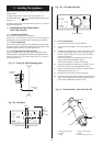
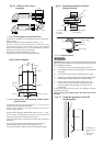
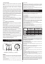
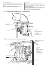
(i) Fit the clamping ring around the flue spigot but leave loose.
From the inside push the assembly through the wall. Align
the flue turret and push fully onto the spigot on the appliance.
(ii) Slide the clamping ring into position so that the hole in
the spigot lines up with the hole in the ring. Tighten the
ring in this position. Through the fixing hole screw the self
drilling screw into the flue (see Fig. 29).
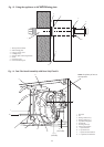
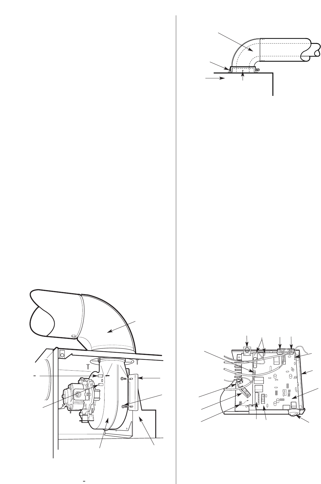
(iii) Remove the fan from the fan/fluehood assembly by
removing the two fan flange fixing screws and also
releasing the fan clamping bracket.
(iv) Disconnect the two end lengths of the pressure sensing
hoses up to and the connection joints (approx 150mm of
hose). Both of these hoses should be discarded. Refer to
Fig. 16.
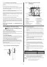
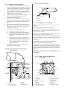
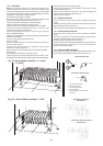
(v) Slide the flue hood only back into the boiler facing the
opposite way to before. Ensure that the flue hood hits the
stops at the rear and the rear combustion chamber slots
in underneath (see Fig. 28).
(vi) With the fluehood on the boiler refit the fan:
(a) Remove the fan lead from the top clip.
(b) With the fan in close proximity to the fluehood re-
attach the fan electrical terminals to the fan. The
polarity of the connection to the fan motor is not
important.
(c) Refit the the fan onto the fluehood. The rear flange
should slide into the clips at the rear of the flue hood.
(d) The fan should then slide upwards into the flue
outlet to enable the fan clamp to be fitted and
tightened into position.
(vii) Re-assemble the front combustion chamber with the 'j'
bolts and replace inner case door.
11.2.13 Completion of the Installation
Check that all the gas and water connections have been
tightened.
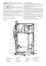
Lower the base plate/control panel. Refer to Fig. 30.
The permanent mains and switched live supply to the boiler
must come from the system junction box. Refer to Fig.11. A 4
core cable is recommended.
Feed the 4 core cable and the pump cables through the bracket
and secure in the cable clamp. Refer to Fig. 30.
Fit all the supply and pump wires to the 5 way plug before fitting
the plug to the socket on the board. This will avoid stress to the
board when using a screwdriver. Refer to Fig.11. for the
connections.
Check that all the cables cannot touch the inner casing.
Test for gas soundness as described in BS6891.
If the appliance is not commissioned immediately, refit the
combustion cover, inner casing cover, base/controls assembly
and the casing. Re-connect the earth connection at the base of
the casing. Check that the gas and electricity services have been
turned off.
REFER NOW TO SECTION 12 - COMMISSIONING THE
APPLIANCE
22
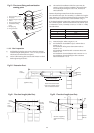
Fig.29 . Flue Turret Fixing .
1
2
3
1. Flue turret assembly
2. Clamp
3. Appliance
4. Fixing screw hole
4
1
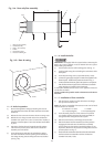
1. Flue hood
2. Fan
3. Sensing connection (+)
4. Sensing connection ( )
2
3 (+)
(Red tube)
4 ( )
(Clear tube)
5
6
7
Fig. 28 . Fan/Flue hood Assembly with
Flue Turret Kit
+
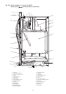
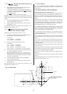
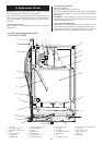
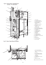
Fig. 30 . Mains electricity and controls
connections.
1
1. Base plate
2. Control board
3. Control knob
4. Fuse 4A
5. External control connector block
6. Earth post
7. Cable clamp
8. Internal earth connection
9. Gas valve connection
10. Mains lead bracket
11. Spark electrode connection
12. Air pressure switch,
temperature sensor,
overheat thermostat
connection
13. Fan connection
14. Flame sense connection
2
3
4
5
6
7
8
9
11
12 13
10
14
5. Flue turret
6. Fan clamp
7. Fan clamp fixing screw