


16
11.1.5 Boiler Preparation
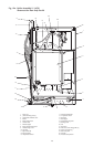
(i) Remove the appliance casing by releasing the screw at
the centre base. Disconnect the earth connection at the base
and lift off.
(ii) Release the four screws and remove the inner casing cover.
(iii) Release the two wing-nuts and remove the combustion
chamber front panel. The cover is located into notches at
the base of the side plates. Leave the stainless steel baffles
in place.
(iv) Disconnect the fan electrical terminals and the sensing
tube from the junction pieces. Slide the flue hood/fan
assembly out of the boiler.
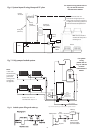
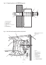
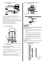
(v) From the literature pack take the self adhesive gasket
and stick around the rear flue opening on the outside of
the casing ensuring that the fixing holes are not blocked
(see Fig. 14b).
11.1.6 Install the Boiler
IMPORTANT: Thoroughly flush the system before connecting the
boiler. Any system cleanser must be flushed from the system
before adding any inhibitor.
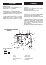
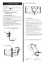
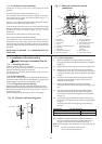
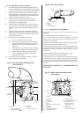
(i) Lift the boiler onto the wall mounting plate. See Fig. 15.
(ii) Level the boiler using the two levelling feet at the base of the
back panel.
(iii) Fit the bottom fixing screw (or optional security screw).
(iv) Connect the gas supply using the nut and olive supplied in the
literature pack - details of the position are shown in Fig. 3.
(v) Connect the flow and return pipes to the system. It is important
that the flow and return pipes are not fixed near to the boiler
using clips that put a strain on the connections.
A drain point should be fitted close to the appliance if bottom
connections are made.
Always consider the possible need to disconnect and remove
the boiler.
11.1.7 Installation of Flue onto Boiler
(i) Pull the flue into position so that the holes in the flange
line up with those in the case
NOTE: The correct rectangular flue restrictor must now be fitted
when the boiler is on the wall.
9/14CBi and 14/19CBi 19/24CBi
66 X 62 (Rectangular) 77 X 62 (Rectangular)
(ii) From the inside, place the correct restrictor in position
over the flue opening and using the screws provided, fix
through the inner casing into the flue system.
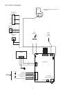
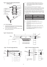
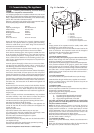
(iii) Slide the inner flue duct with fixing bar into the flue.
(iv) Slide the fluehood and fan assembly back into position
engaging the fan outlet into the inner duct assembly
and reconnect the fan electrical terminals (polarity is not
important). Reconnect the pressure sensing tubes onto the
junction pieces. See Fig. 16.
(v) Ensure that the combustion chamber is slotted underneath
the flue hood and re-assemble with the combustion
chamber front and 'J' bolts.
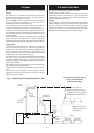
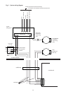
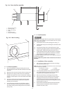
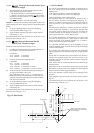
Fig. 14a . Rear only flue assembly
Tape
L + 5
1
2
4
5
6
3
1. Telescopic flue assembly
2. Terminal assembly
3. Flange / flue assembly
4. Indents
5. Wall mounting plate
6. Flue tube with fixing bar
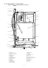
Fig. 14b . Rear of casing
Gasket