


RWB 6104 BNX R02 Page 9
Start Burner and Set Combustion
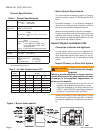
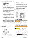
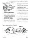
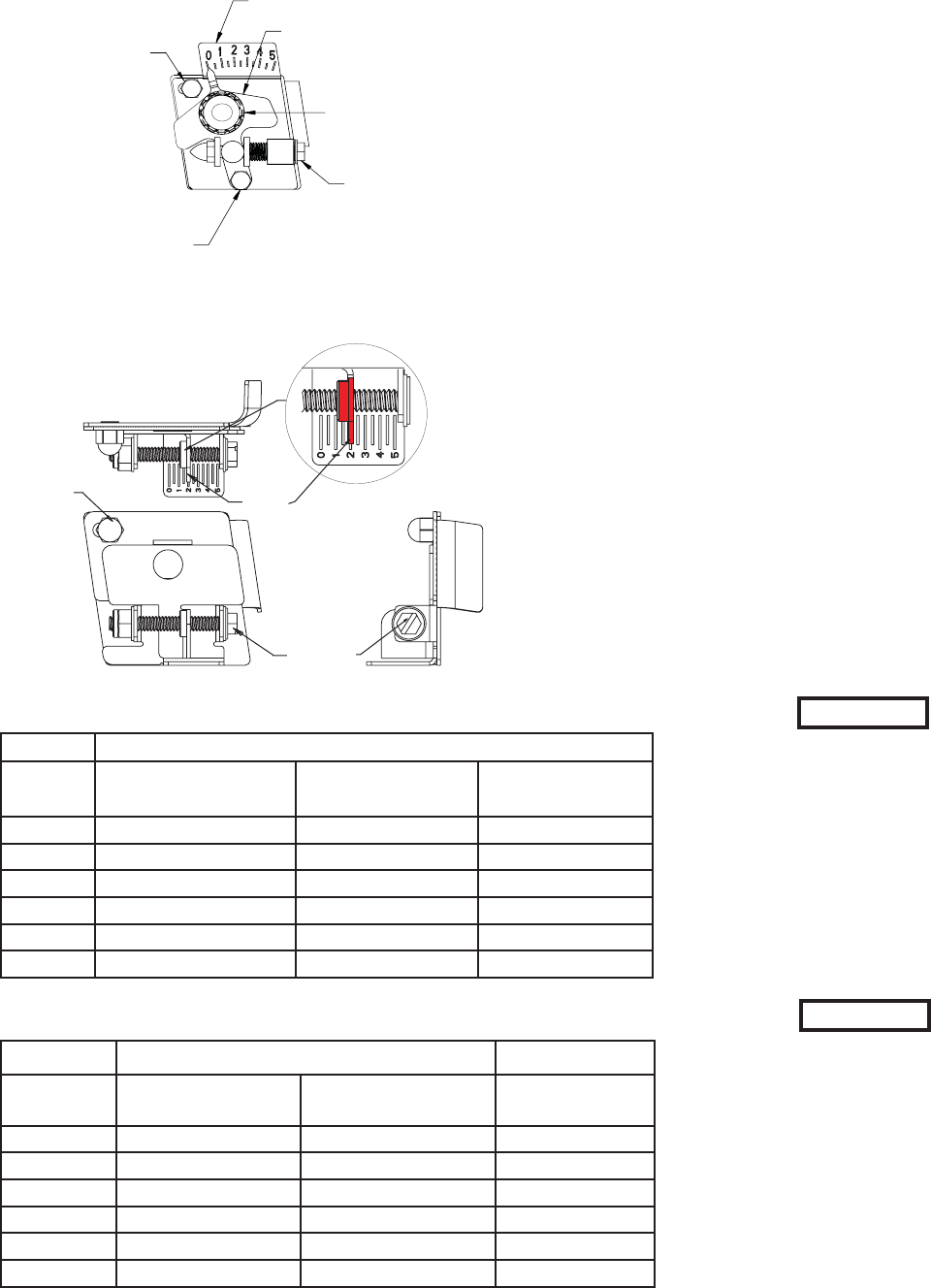
Check/Adjust Zero Calibration for older style
Head/Air Adjustment Mechanism. Refer to
Figure 5a.
Loosen the splined nut and lower acorn nut
approximately one turn. (DO NOT loosen the
upper acorn nut. This is used only for setting
the zero adjustment.) (See Figure 5a.)
A 5/16” nut driver or fl at blade screwdriver
can be used to turn the adjustment screw for
head/air setting.
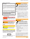
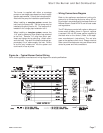
Check/Adjust Zero Calibration for newer style
Head/Air Adjustment Mechanism. Refer to
Figure 5b.
Slightly loosen the zero setting acorn.
Turn the screw until the reading is set to zero.
(Mid-point of pointer should line up with zero.
Turn the air adjustment screw counterclock-
wise to adjust the plate with the pointer to the
zero position.
Slide the nozzle line assembly forward until
the retention head engages the fi xed stops in
the retention ring at the end of the air tube.
Tighten the zero setting acorn nut.
The rear door must be closed. The adjustment
screw may now be turned clockwise to adjust
the head/air setting.
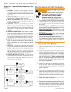
Turn the adjusting screw to a setting 1/2 num-
ber lower than the proper setpoint as indicated
in Tables 3a and 3b. Then turn the adjusting
screw counterclockwise to the proper setting.
Tighten the spline nut after the head/air setting
has been adjusted.
7.
a.
b.
8.
a.
b.
c.
d.
e.
f.
g.
h.
NX Air Tube & Head Combinations
Head/Air
Setting
LG - (9-slot head)
LH - (6-slot head)
LB - (9-slot head)
LC - (6-slot head)
LD - (9-slot head)
LF - (6-slot head)
0.5 0.40 – 0.50 -- 1.10 – 1.25
1.0 0.45 – 0.60 -- 1.20 – 1.35
2.0 0.55 – 0.70 0.85 – 1.05 1.30 – 1.45
3.0 0.65 – 0.80 0.95 – 1.15 1.40 – 1.55
4.0 0.75 – 0.90 1.05 – 1.25 1.50 – 1.65
5.0 0.85 – 1.00 1.15 – 1.35 1.60 – 1.75
Table 3a. – NX Burners
NX Air Tube & Head Combinations
Head/Air
Setting
LG - (9-slot head)
LH - (6-slot head)
LB - (9-slot head)
LC - (6-slot head)
LD - (9-slot head)
LF - (6-slot head)
0.5 – 0.40 – 0.60 –
1.0 0.40 – 0.55 0.50 – 0.70 1.10 – 1.25
2.0 0.50 – 0.65 0.60 – 0.80 1.20 – 1.35
3.0 0.60 – 0.75 0.70 – 0.90 1.30 – 1.45
4.0 0.70 – 0.85 0.80 – 1.00 1.40 – 1.55
5.0 0.80 – 0.95 0.90 – 1.10 –
Table 3b. – NX Burner with Low Fire Rate Baffl e (LFRB)
Installed
Use factory-set or manufacturer’s
recommended Head/Air Setting
for ‘Starting the Burner and Set-
ting Combustion’. The Head/Air
Settings shown in Figures 3, are
provided for reference purposes
and represent a general range of
rates and settings. Individual ap-
pliances, vent systems, and fi eld
conditions will impact the overall
burner set up required for satis-
factory combustion performance.
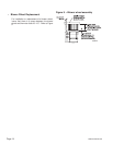
NOTICE
The NX burner has a reduced diam-
eter air tube, precision-designed air
throttle cup and combustion head for
improved performance. This design
provides very accurate control of the
air/fuel ratio, but the light reaching
the cad cell through small holes in
these components is limited. Be-
cause of this, the average cad cell
resistance may be higher than
conventional burners with larger
openings.
NOTICE
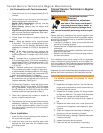
Pointer
Zero Setting
Locking Nut
Adjustment
Screw
Am52000
Figure 5b. – New Style Head/air Adjustment
Plate
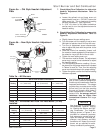
Figure 5a. – Old Style Head/air Adjustment
Plate
Upper Acorn Nut
(Lock Zero
Calibration)
Lower Acorn Nut
(Lock Air Setting)
Scale
Pointer
Splined
Nut
Adjustment
Nut
SK9667